Deep hole blasting explosive feeding equipment and method

A technology of deep hole blasting and drug delivery, which is applied in the direction of drilling equipment and methods, blasting, drilling equipment, etc., and can solve problems such as poor spring clamping effect, safety accidents, and impact on pre-splitting blasting, so as to ensure pre-splitting The effect of the explosion effect

Active Publication Date: 2022-02-15
ANHUI UNIV OF SCI & TECH
View PDF6 Cites 1 Cited by
  • Summary
  • Abstract
  • Description
  • Claims
  • Application Information

AI Technical Summary

Problems solved by technology

If the hard roof cannot collapse in time after the mining of the working face, when the working face is advancing, the overhanging area of ​​the hard roof in the stope will be too large, which will cause very strong initial pressure and periodic pressure, and if it is serious, it will cause impact Ground pressure, coal and gas outburst and other strong mine pressure problems, and then cause economic losses and casualties
[0003]Deep hole pre-splitting blasting can effectively change the stress distribution of the hard roof, thereby reducing the occurrence of strong mine pressure. However, for ultra-deep hole pre-splitting blasting, due to the depth of drilling It is very deep, and the drug delivery has become a very difficult problem. Now the ultra-deep hole drug delivery is driven by the drill pipe to move the powder column to the blasting position. Heating after friction can easily cause safety accidents. At the same time, when the grain is sent to the blasting position, it is locked by the spring piece. burst blast effect

Method used


Image

  • Deep hole blasting explosive feeding equipment and method
  • Deep hole blasting explosive feeding equipment and method
  • Deep hole blasting explosive feeding equipment and method

Examples


Embodiment

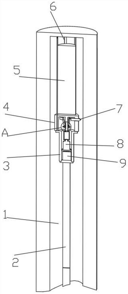
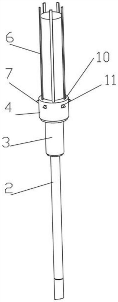
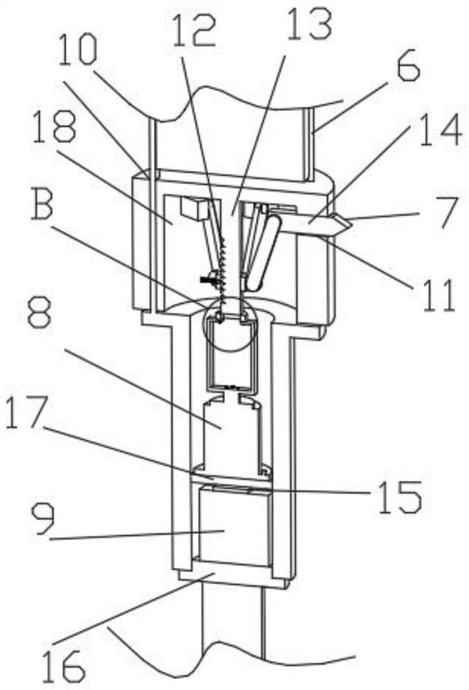
[0035] Such as Figure 1-3 , 5 and 8, a kind of deep-hole blasting charge delivery equipment includes a drill hole 1, a drill pipe 2 and a charge column 5, the top of the drill pipe 2 is connected with a limit structure, and the limit structure includes a clamping tube 4, an arc limit The position plate 6, the base 16 and the top ring 27, the top of the base 16 is threadedly connected with the straight cylinder 3, the top of the straight cylinder 3 is connected with the top ring 27, and the top of the top ring 27 is evenly fixed and connected with the arc-shaped limiting plate 6 along the circumferential direction, and the drug column 5. The outer wall is in contact with the inner wall of the arc-shaped limiting plate 6;

[0036] The grain 5 is placed in the limit structure, and the arc-shaped limit plate 6 of the limit structure limits the position of the grain 5. When the grain 5 moves, it will not contact the inner wall of the borehole 1, and there will be no sliding fricti...


PUM


Abstract

The invention discloses deep hole blasting explosive feeding equipment and method, and relates to the technical field of deep hole blasting. The deep hole blasting explosive feeding equipment comprises a drill hole, a drill rod and an explosive column, wherein the top of the drill rod is connected with a limiting structure, a pushing structure is connected in the limiting structure, the top of the limiting structure is connected with a clamping structure, the top of the clamping structure is connected with an explosive column in an attached mode, and the outer wall of the explosive column is connected with the limiting structure; when the explosive column moves to the blasting position, the pushing structure pushes the clamping structure to be unfolded, the clamping structure is unfolded and fixed to the inner wall of the drill hole in an inserted mode, and the explosive column is accurately and stably clamped to the blasting position. By means of the mode, the explosive column is placed in the limiting structure, the arc-shaped limiting plate of the limiting structure limits and protects the explosive column, the explosive column does not make contact with the inner wall of a drill hole when moving, the sliding friction phenomenon does not occur, and explosive feeding is safer.

Description

technical field [0001] The invention relates to the technical field of deep hole blasting, in particular to a deep hole blasting drug delivery device and method. Background technique [0002] Hard roofs are distributed in various mining areas in my country, and have always been a difficult problem that needs to be paid attention to and solved. If the hard roof cannot collapse in time after the mining of the working face, when the working face is advancing, the overhanging area of ​​the hard roof in the stope will be too large, which will cause very strong initial pressure and periodic pressure, and if it is serious, it will cause impact Ground pressure, coal and gas outburst and other strong mine pressure problems will cause economic losses and casualties. [0003] Deep hole pre-splitting blasting can effectively change the stress distribution of the hard roof, thereby reducing the occurrence of strong rock pressure. The drill pipe pushes the charge column to move to the b...

Claims


Application Information

Patent Timeline
IPC IPC(8): F42D1/08F42D3/04E21B7/00
CPCF42D1/08F42D3/04E21B7/007
Inventor 李康康孔坤
Owner ANHUI UNIV OF SCI & TECH
Why Eureka
Try Eureka