Miniature circuit breaker arc extinguishing system and miniature circuit breaker with same

A small circuit breaker and arc extinguishing technology, applied in the direction of circuit breaker parts, circuits, electrical components, etc., can solve the problems of stagnant arc energy and inability to dissipate efficiently

Pending Publication Date: 2022-02-15
XIAN UNIV OF TECH +1
View PDF0 Cites 0 Cited by
  • Summary
  • Abstract
  • Description
  • Claims
  • Application Information

AI Technical Summary

Problems solved by technology

[0004] Therefore, the technical problem to be solved by the present invention is to overcome the defects that the arc generated by the miniature circuit breaker in the prior art will stagnate between the static contact and the moving contact and the arc energy cannot be efficiently dissipated, thereby providing a miniature circuit breaker Arc extinguishing system and miniature circuit breaker with it

Method used


Image

  • Miniature circuit breaker arc extinguishing system and miniature circuit breaker with same
  • Miniature circuit breaker arc extinguishing system and miniature circuit breaker with same
  • Miniature circuit breaker arc extinguishing system and miniature circuit breaker with same

Examples


Embodiment 1

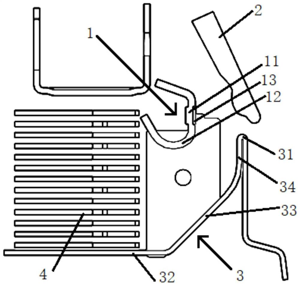
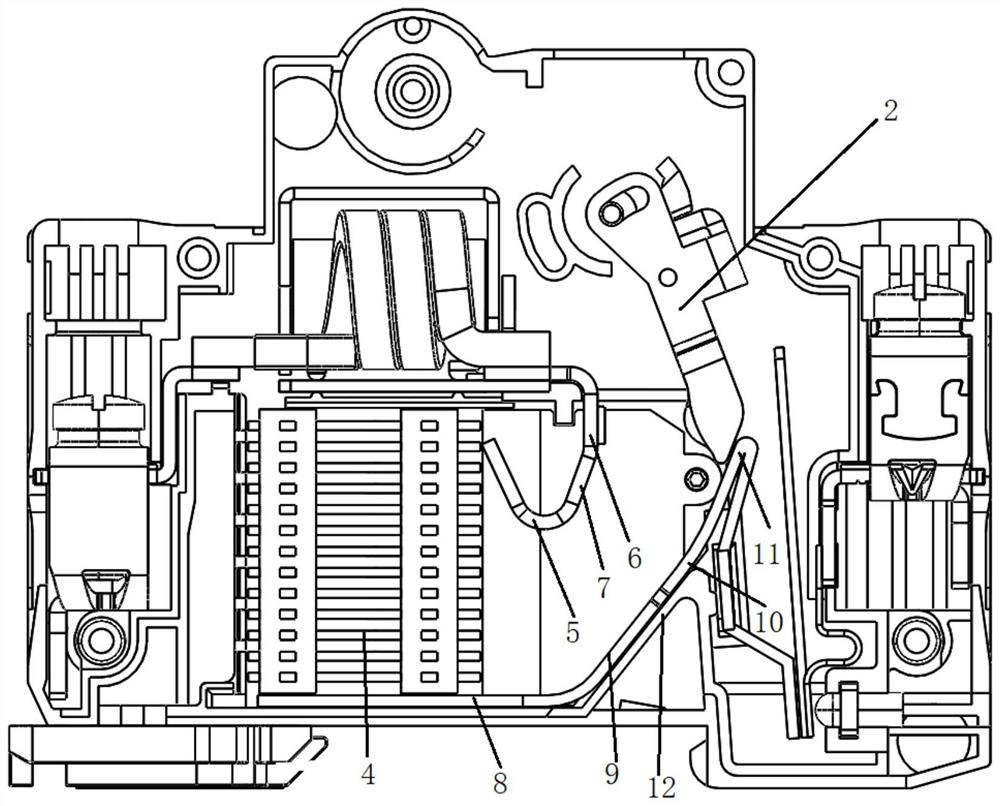
[0033] Such as figure 2 As shown, an arc extinguishing system for a small circuit breaker provided in this embodiment includes: a static contact 1 , a moving contact 2 and a lower running arc 3 installed in the housing.

[0034] The static contact 1 is provided with a hook-shaped arc-leading foot 5 , a vertical portion 6 provided with a static contact, and a first inclined portion 7 connecting the arc-leading foot 5 and the vertical portion 6 . The arc-leading pin 5 is an arc or a "V" shape. The arc-leading foot 5 in this embodiment is arc-shaped. The first inclined portion 7 is inclined in the direction away from the static contact, and the angle between the first inclined portion 7 and the vertical portion 6 ranges from 155° to 175°. In this embodiment, the first inclined portion 7 and the vertical portion 6 The angle between the vertical parts 6 is 175°.

[0035] The lower running arc 3 is provided with a horizontal portion 8, an oblique portion, a second oblique portio...

Embodiment 2

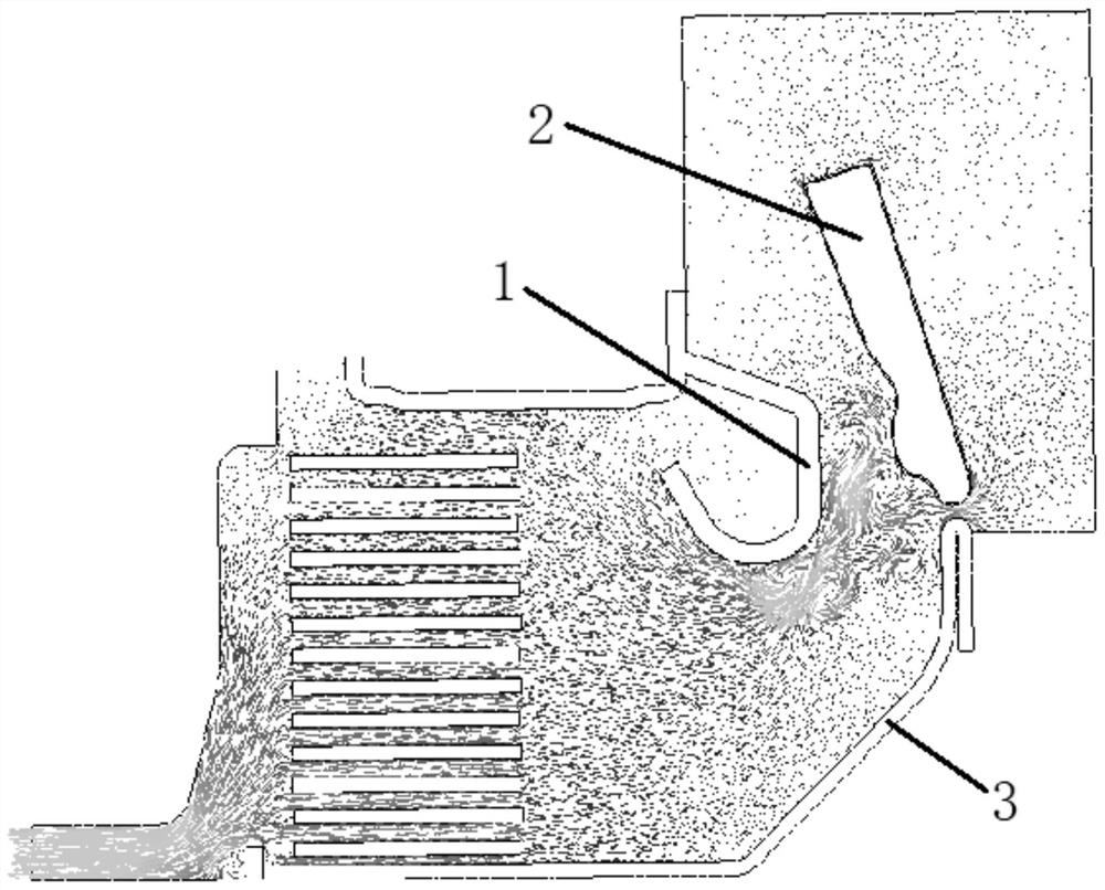
[0042] This embodiment provides a miniature circuit breaker with the miniature circuit breaker arc extinguishing system described in Embodiment 1. The housing of the miniature circuit breaker arc extinguishing system is closed so that the static contact, the moving contact and the lower running arc are in the Work in enclosed spaces. When the miniature circuit breaker is working, it can achieve rapid arc ignition and arc extinction, reduce the formation of eddy currents, enhance the convective dissipation of arc energy, and the efficient convective dissipation makes the arc quickly cool and extinguish, thereby improving the electrical life of DC products. The critical current breaking capability makes the product performance more reliable.


PUM


Abstract

The invention relates to the technical field of circuit breaker arc extinguishing, in particular to a miniature circuit breaker arc extinguishing system and a miniature circuit breaker with the same. The miniature circuit breaker arc extinguishing system comprises a static contact which is provided with a hook-shaped arc strike pin, a vertical part provided with a static contact and a first inclined part connecting the arc strike pin and the vertical part, the first inclined part being inclined towards the direction deviating from the static contact, and the included angle between the first inclined part and the vertical part being smaller than or equal to 175 degrees; a lower arc running way, provided with a second inclined part and a corner part which are connected in sequence, and the angle between the second inclined part and the vertical part being not smaller than the angle between the first inclined part and the vertical part; and a moving contact, in contact with the corner part when moving to the maximum opening distance position in the breaking state. When the moving contact moves to the maximum opening distance, the gap between the lower arc running channel and the second inclined part is blocked, the pressure gradient from the contact area to the air outlet is enhanced, and rapid arc striking and extinguishing can be realized.

Description

technical field [0001] The invention relates to the technical field of circuit breaker arc extinguishing, in particular to a small circuit breaker arc extinguishing system and a small circuit breaker with the same. Background technique [0002] Miniature circuit breakers are also called air switches because their arc extinguishing medium is mainly air. With the goal of "carbon peaking and carbon neutrality" put forward in China, the photovoltaic power generation capacity of clean energy is increasing year by year, and the miniature circuit breaker is used as the control and protection electrical appliance of the photovoltaic power generation system. Arc performance puts forward higher requirements. The critical current breaking and electrical life of DC circuit breakers have become the focus and difficulty of the R&D and design of miniature circuit breakers. For miniature circuit breakers, the arc extinguishing performance is not only related to the selection of parts such...

Claims


Application Information

Patent Timeline
IPC IPC(8): H01H73/18H01H9/34
CPCH01H73/18H01H9/34
Inventor 尹健宁刘超李兴文卢权胜
Owner XIAN UNIV OF TECH
Why Eureka
Try Eureka