Supercharge Your Innovation With Domain-Expert AI Agents!

Spiral dynamic reciprocating scanning optical system

An optical system and reciprocating scanning technology, which is applied in the field of laser scanning optical systems, can solve the problems of missed scanning, inability to completely cover the surface to be scanned, and non-coincident translation directions, so as to increase adaptability, avoid missing scanning problems, and improve scanning quality and processing efficiency

Pending Publication Date: 2022-02-18
廊坊元拓科技有限公司
View PDF0 Cites 2 Cited by
  • Summary
  • Abstract
  • Description
  • Claims
  • Application Information

AI Technical Summary

Benefits of technology

This patented technology allows for better control over how much light energy falls on an area during a process called scanning. It uses special shapes that are made up by curved lines instead of regular circles like those used previously. By doing this, it prevents leaks from being caused due to imperfections such as inclined surfaces or slow movement at high speeds. Additionally, ZigZags scans may also help reduce glare problems while moving around smoothly without interfering too well with other processes. Overall, these technical improvements enhance the accuracy and effectiveness of scanners' performance.

Problems solved by technology

This patented technical problem addressed in the patents relates to improving the accuracy and efficiency of lasers used during manufacturing processes such as machining operations where irregularities can occur due to factors like vibrations caused by other equipment or changes over time (such as temperature).

Method used


Image

  • Spiral dynamic reciprocating scanning optical system
  • Spiral dynamic reciprocating scanning optical system

Examples


Embodiment Construction

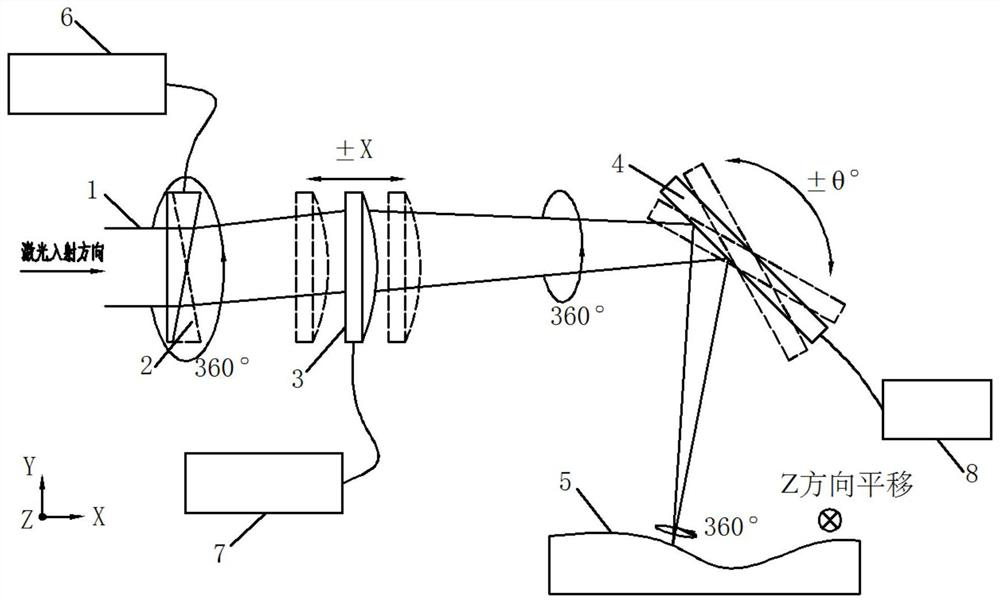
[0017] See figure 1 , a helical dynamic reciprocating scanning optical system, comprising a vibrating mirror scanning device and a workpiece 5 to be scanned, the vibrating mirror scanning device sequentially includes a deflecting prism 2, a dynamic focusing mirror 3, and a swinging vibrating mirror 4 according to the optical path , wherein, the deflection prism 2 is a prism whose one side is inclined to the optical axis and the other side is perpendicular to the optical axis, and the deflection prism 2 is controlled by a rotation controller 6 to rotate 360° uninterruptedly around its optical axis; The dynamic focusing mirror 3 is controlled by a reciprocating linear motion controller 7, and performs a reciprocating linear motion along the X-axis direction; the oscillating vibrating mirror 4 is controlled by a reciprocating swing controller 8, and performs a reciprocating swing motion in the X-Y plane around its central axis; The workpiece 5 makes a reciprocating linear motion ...


PUM


Abstract

The invention relates to a spiral dynamic reciprocating scanning optical system which comprises a galvanometer scanning device and a workpiece (5) to be scanned, the galvanometer scanning device sequentially comprises a deflection prism (2), a dynamic focus lens (3) and a swing galvanometer (4) according to a light path, one side of the deflection prism (2) is inclined to an optical axis, the other side of the deflection prism (2) is perpendicular to the optical axis, the deflection prism (2) continuously rotates by 360 degrees around the optical axis of the deflection prism (2); the dynamic focus lens (3) does reciprocating rectilinear motion along the X-axis direction; the swinging galvanometer (4) swings back and forth in an X-Y plane around the central axis of the swinging galvanometer (4); the workpiece (5) does reciprocating rectilinear motion in the Z-axis direction. The optical system outputs the scanning laser beam with the motion trail in a spatial spiral shape, can be suitable for the workpiece with the uneven surface to be scanned, can avoid the problem of missing scanning, and remarkably improves the scanning quality and the machining efficiency.

Description


Claims


Application Information

Patent Timeline
Owner 廊坊元拓科技有限公司
Features
  • R&D
  • Intellectual Property
  • Life Sciences
  • Materials
  • Tech Scout
  • Unparalleled Data Quality
  • Higher Quality Content
  • 60% Fewer Hallucinations
Learn More