Four-drive energy adjustable continuous winged variable dip angle direct-acting aircraft

A four-drive, continuous-belt technology, applied in aircraft, motor vehicles, aircraft parts, etc., can solve the problems of inability to achieve vertical take-off and landing and hovering in the air, restricting the popular application of flapping-wing aircraft, and low overall efficiency of flapping-wing aircraft. , to achieve the effect of simple structure, low production cost and good action consistency

Pending Publication Date: 2022-02-18
GLOBAL INST OF SOFTWARE TECH
View PDF0 Cites 1 Cited by
  • Summary
  • Abstract
  • Description
  • Claims
  • Application Information

AI Technical Summary

Problems solved by technology

The main reason for the overall low efficiency of flapping wing aircraft is that most of the current research simply imitates the shape and flapping motion of the wings of birds or insects, but it is difficult to realize the use of the wing's own posture and structure in the process of flapping wings of flying creatures. The change of air resistance reduces air resistance and generates unsteady aerodynamic force, and the resulting low aerodynamic efficiency seriously restricts the popularization and application of flapping-wing aircraft
At the same time, most of the current flapping-wing aircraft cannot achieve vertical take-off and landing and hovering in the air, and their flexibility and maneuverability are not good enough

Method used


Image

  • Four-drive energy adjustable continuous winged variable dip angle direct-acting aircraft
  • Four-drive energy adjustable continuous winged variable dip angle direct-acting aircraft
  • Four-drive energy adjustable continuous winged variable dip angle direct-acting aircraft

Examples


Embodiment 1

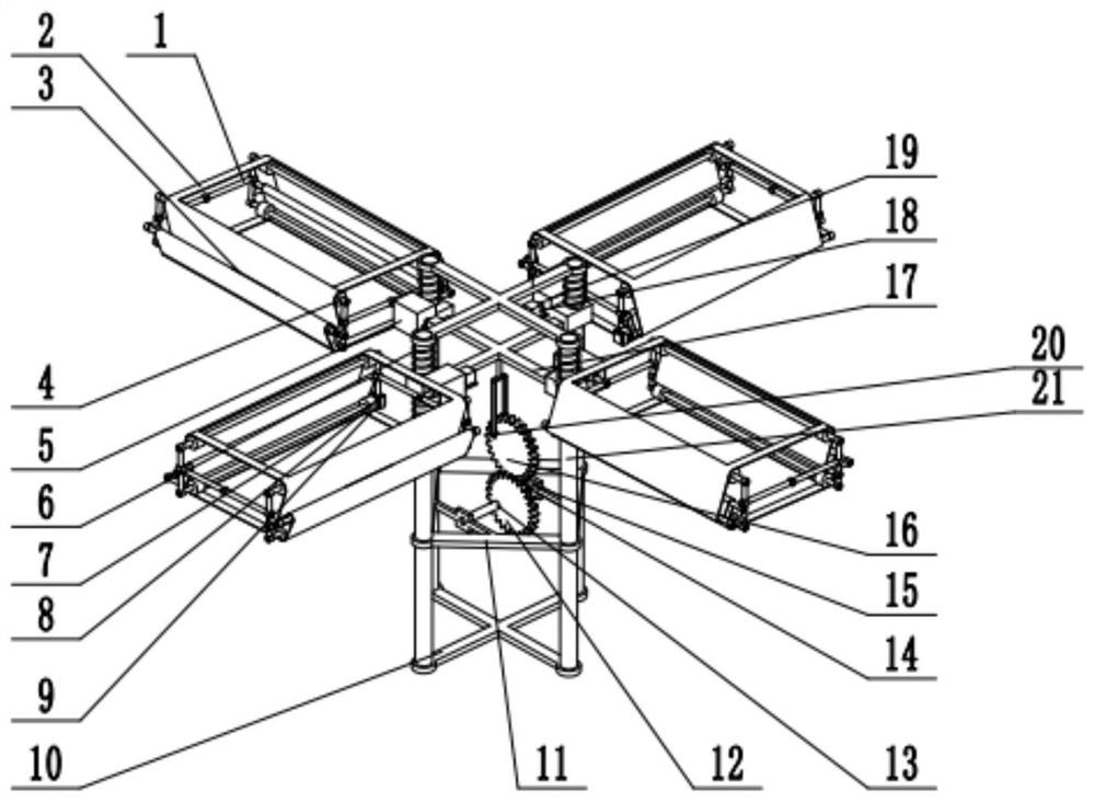
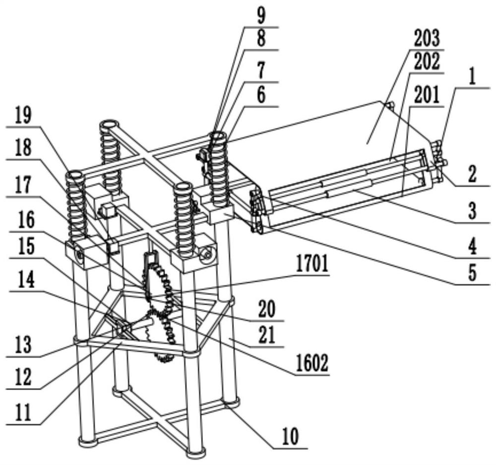
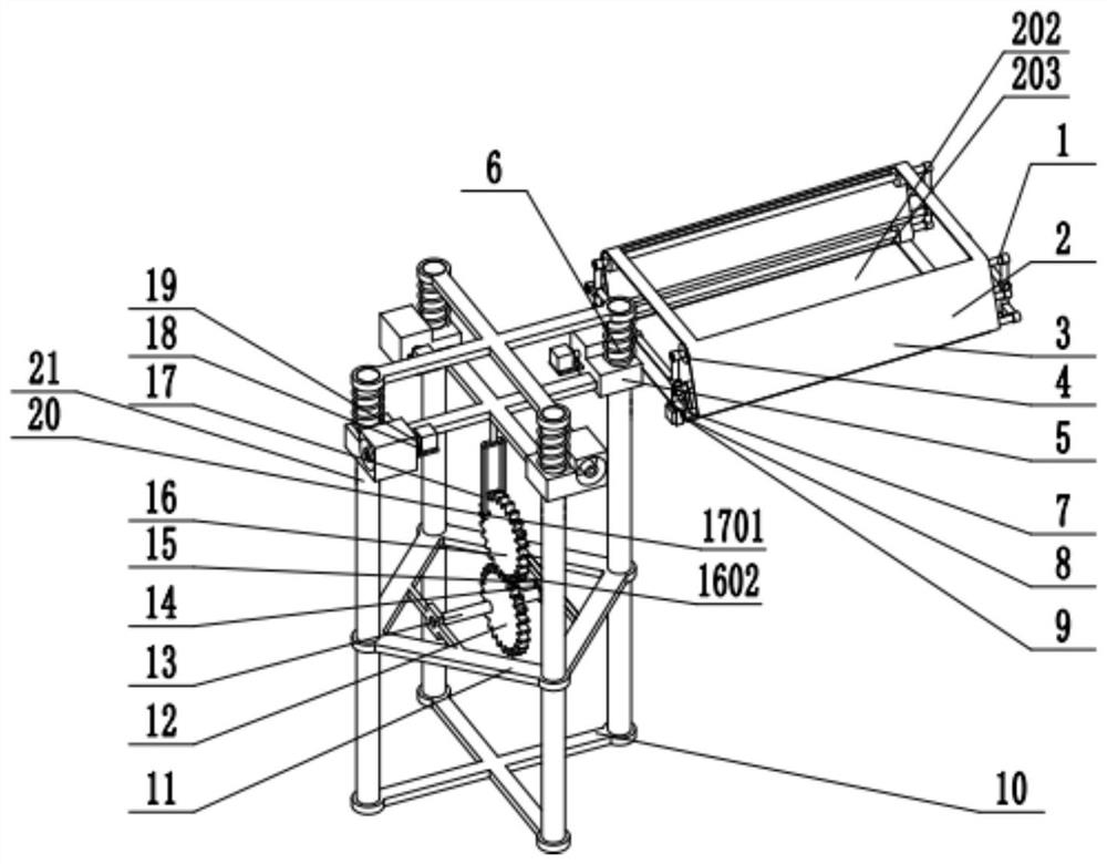
[0036] Example 1: Combining figure 1 , figure 2 , image 3 , Figure 4 , Figure 5 , Figure 6 , Figure 7 , Figure 8 , Figure 9 , Figure 10 and Figure 11 , a high-voltage wire inspection UAV using a four-drive energy-adjustable continuous belt-wing variable-inclination direct-motion aircraft. Such as figure 1 As shown, in the present application, the four-drive energy-adjustable continuous winged variable inclination direct motion aircraft includes a winged frame 1, a soft belt 2, a tension pulley 3, a pulley 4, a connecting piece 5, a spring 6, a stepping Motor 7, first reducer 8, pulley transmission shaft 9, fuselage shell 10, fuselage frame 11, driving eccentric gear 12, transmission shaft 13, motor 14, second reducer 15, driven eccentric gear 16, push Rod 17, stepper motor 18, third reducer 19, pin shaft 20 and slideway 21. Such as Figure 6 and Figure 7 As shown, there are frame left longitudinal beam 101, frame connecting rod 102, frame right longitu...

Embodiment 2

[0037] Example 2: Combining figure 1 , figure 2 , image 3 , Figure 4 , Figure 5 , Figure 6 , Figure 7 , Figure 8 , Figure 9 , Figure 10 and Figure 11 , a high-rise building fire-fighting drone that uses a four-drive energy-adjustable continuous belt-wing variable-inclination direct-acting aircraft. It includes a winged frame 1, a soft belt 2, a tensioning wheel 3, a pulley 4, a connecting piece 5, a spring 6, a stepping motor 7, a first reducer 8, a pulley drive shaft 9, a fuselage shell 10, a machine Body frame 11, driving eccentric gear 12, transmission shaft 13, motor 14, second reducer 15, driven eccentric gear 16, push rod 17, stepper motor 18, third reducer 19, pin shaft 20 and slideway 21 . Such as Figure 6 and Figure 7 As shown, there are frame left longitudinal beam 101, frame connecting rod 102, frame right longitudinal beam 104, motor mounting hole 105, tensioning wheel mounting rod 107, frame beam 108 and winged rotating shaft 103 on the wing...


PUM


Abstract

The invention relates to a four-drive energy adjustable continuous winged variable dip angle direct-acting aircraft. Four vertical slideways are symmetrically mounted and fixed on the periphery of the fuselage frame, the four connecting pieces are respectively connected to the four slideways in a sliding manner, the four belt wings are respectively connected to the four connecting pieces and can rotate relatively, and each belt wing comprises a belt wing frame and a soft belt mounted on the belt wing frame; a belt wheel, a tensioning wheel and a driving motor are further arranged in the winged frame and used for switching between the working state and the reset state of the winged frame, the transmission mechanism is connected to the four connecting pieces, and the motor arranged on the fuselage frame drives the transmission mechanism to move after being decelerated through a second speed reducer so that the four connecting pieces can synchronously slide up and down. The four stepping motors arranged on the four connecting pieces correspondingly drive the four belt wings to rotate after being decelerated through the four third speed reducers.

Description

technical field [0001] The invention relates to the field of movable-wing aircraft and flying robots, in particular to a direct-moving aircraft for four-drive energy-adjustable continuous-wing variable-inclination angles. Background technique [0002] There are three flight types of aircraft flying: fixed wing, rotary wing and flapping wing. Among them, flapping wing flight is the flying mode adopted by flying creatures in nature. It mainly uses the up and down flapping of the wings to generate lift and thrust at the same time. , hovering and propulsion functions are based on one body, and at the same time have strong maneuverability and flexibility, and are more suitable for flying around obstacles. For small-sized and low-speed aircraft flying under low Reynolds numbers, the unsteady lift generated by the flapping wing is much greater than the constant lift of the fixed wing; from the perspective of thrust, the propulsion efficiency of the flapping wing is higher than that...

Claims


Application Information

Patent Timeline
Patent Type & Authority Applications(China)
IPC IPC(8): B64C39/00B64C21/08B64D27/24
CPCB64C39/003B64C21/08B64D27/24
Inventor 廖振强朱佾王一迪赵雪盛松梅邱明夏青元
Owner GLOBAL INST OF SOFTWARE TECH
Why Eureka
Try Eureka