
Expansion joint and pipe section arrangement and control method thereof

A technology for expansion joints and pipe sections, which is applied in the field of expansion joints and their pipe section layout and control, can solve the problems of easy damage of stainless steel corrugated pipes, affecting the life of the piping system, and the influence of pipe stress, etc., to achieve long service life, prolong service life, alleviate The effect of pipe section vibration

Pending Publication Date: 2022-02-22
JIANGSU UNIV OF SCI & TECH
View PDF13 Cites 0 Cited by
  • Summary
  • Abstract
  • Description
  • Claims
  • Application Information

AI Technical Summary

Problems solved by technology

[0002] In the process of pipeline layout, it is often necessary to add Π-shaped network pipes at a certain distance to reduce the secondary stress caused by factors such as changes in pipeline temperature. Or fatigue damage, which affects the life of the entire piping system; in addition, another way to solve the secondary stress is to use expansion joints, but due to domestic process problems, the stainless steel bellows of the expansion joints are easily damaged, resulting in leakage problems, and the expansion joints leak in specific In engineering practice, the remedial measures are complex and easily have a great impact on the stress of the pipeline, thus endangering the safety of the entire pipeline system

Method used


Image

  • Expansion joint and pipe section arrangement and control method thereof
  • Expansion joint and pipe section arrangement and control method thereof
  • Expansion joint and pipe section arrangement and control method thereof

Examples


Embodiment Construction

[0026] The present invention will be further described below in conjunction with accompanying drawing.

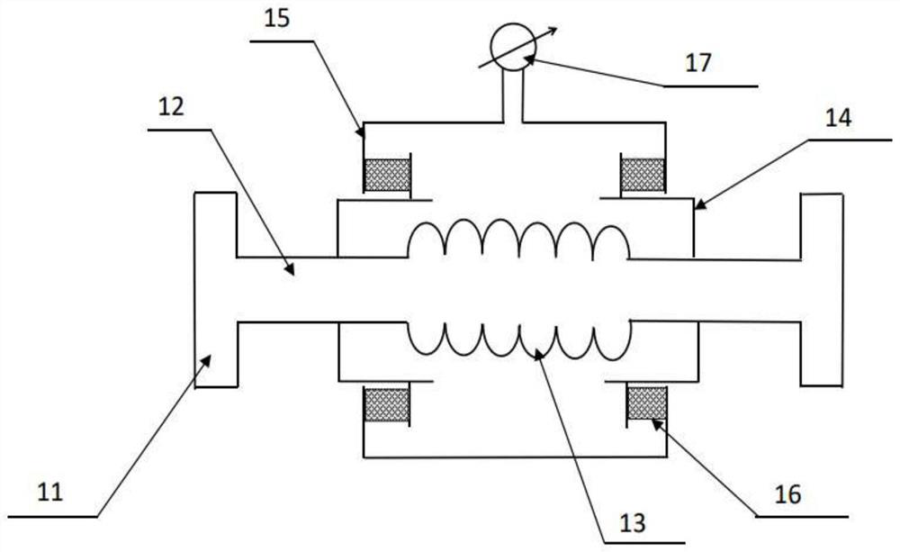
[0027] Such as figure 1 As shown, the expansion joint 1 of the present invention includes a flange 11, a connecting pipe 12, a bellows 13, a first cavity shell 14, a second cavity shell 15, a gasket block 16, and a pressure gauge 17, wherein the bellows The two ends of 13 are symmetrically welded with a connecting pipe 12, and the end of the connecting pipe 12 is welded with a flange 11, which is used for the connection between the expansion joint 1 and the pipe section. Welded with the bellows 13, on the one hand, it acts as a connection, and on the other hand, it is also the main supporting frame of the expansion joint 1.

[0028] The outer side of the bellows 13 is covered with a first cavity shell 14, the two ends of the first cavity shell 14 are respectively welded with the connecting pipe 12, the outer side of the first cavity shell 14 is set with a second cavity she...


PUM


Abstract

The invention discloses an expansion joint and a pipe section arrangement and control method thereof. The expansion joint comprises a corrugated pipe, the two ends of the corrugated pipe are symmetrically connected with connecting pipes, the outer side of the corrugated pipe is sleeved with a first cavity shell, the two ends of the first cavity shell are fixed to the connecting pipes correspondingly, the outer side of the first cavity shell is sleeved with a second cavity shell, a sealing cushion block is arranged between the first cavity shell and the second cavity shell, the second cavity shell is connected with a pressure meter, and the first cavity shell, the second cavity shell, the sealing cushion block and the pressure meter jointly form a closed air chamber together with the connecting pipes and the corrugated pipe. According to the expansion joint, a method that the flexible cushion block and the corrugated pipe jointly reduce secondary stress is adopted, so that partial axial deformation can be provided, transverse deformation can also be provided, meanwhile, the flexible cushion block can have a good buffering effect on blind plate force of a pipeline system, and can well protect the corrugated pipe from being stretched by the blind plate force to be damaged, and thus, the expansion joint can be better used in pipeline design, so that a pipeline system is more stable.

Description

technical field [0001] The invention relates to an expansion joint, in particular to an expansion joint and a pipe section layout and control method thereof. Background technique [0002] In the process of pipeline layout, it is often necessary to add Π-shaped network pipes at a certain distance to reduce the secondary stress caused by factors such as changes in pipeline temperature. Or fatigue damage, which affects the life of the entire piping system; in addition, another way to solve the secondary stress is to use expansion joints, but due to domestic process problems, the stainless steel bellows of the expansion joints are easily damaged, resulting in leakage problems, and the expansion joints leak in specific In engineering practice, the remedial measures are complex and easily have a great impact on the stress of the pipeline, thus endangering the safety of the entire pipeline system. Contents of the invention [0003] Purpose of the invention: The purpose of the in...

Claims


Application Information

Patent Timeline
Patent Type & Authority Applications(China)
IPC IPC(8): F16L51/02F16L51/03F16L55/02F17D3/01F17D5/00F17D5/02
CPCF16L51/02F16L51/03F16L55/02F17D3/01F17D5/00F17D5/02
Inventor 李秀窦培林赵世发刘明琛
Owner JIANGSU UNIV OF SCI & TECH
Learn More