Battery compartment

A technology for battery compartments and batteries, which is applied in the field of battery compartments and can solve problems such as long replacement time and battery shaking

Inactive Publication Date: 2022-02-22
GUANGDONG BOZHILIN ROBOT CO LTD
View PDF6 Cites 0 Cited by
  • Summary
  • Abstract
  • Description
  • Claims
  • Application Information

AI Technical Summary

Problems solved by technology

For this reason, the present invention proposes a battery compartment, which is fast and convenient for assembling and positioning the battery, and is stable after assembling the battery, which solves the problems of long replacement time and shaking of the battery after assembly due to inconvenient disassembly and assembly of the battery

Method used


Image

  • Battery compartment
  • Battery compartment
  • Battery compartment

Examples


Embodiment 1

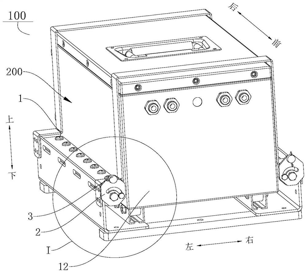
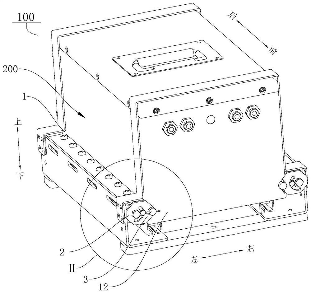
[0081] A battery compartment 100, such as figure 1 and figure 2 As shown, it includes: a warehouse body 1 , a first limiting member 2 and a second limiting member 3 .

[0082] Wherein, the bin body 1 is provided with an installation cavity, and the installation cavity is suitable for storing the battery 200 , and the bin body 1 is formed with an entrance 12 communicating with the installation cavity. The two first limiting members 2 are respectively arranged at the entrance and exit 12, and each first limiting member 2 can be switched between the first position and the second position, such as figure 1 As shown, in the first position, the first limiting member 2 is located outside the entrance and exit 12; as figure 2 As shown, in the second position, the second limiting member 3 blocks the entrance and exit 12 .

[0083] like figure 1 and figure 2 As shown, the second limiting member 3 is installed on the first limiting member 2, and when the first limiting member 2 m...

Embodiment 2

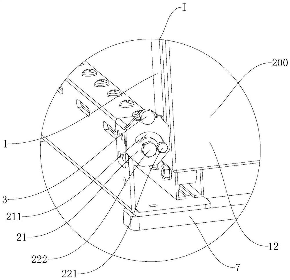
[0085] A battery compartment 100, different from Embodiment 1, on the basis of Embodiment 1, such as Figure 5 As shown, the first limiting member 2 includes: a baffle plate 21 and a matching plate 22 , the matching plate 22 is connected to the bin body 1 near the entrance 12 , and the baffle plate 21 is eccentrically rotatably connected to the matching plate 22 through a rotating shaft 222 . like image 3 As shown, one end of the baffle plate 21 protrudes to form a stop plate 212 , and the second limiting member 3 is arranged on the stop plate 212 . like image 3 and Figure 4 As shown, the baffle plate 21 is provided with an arc-shaped limiting groove 211 , and the matching plate 22 is provided with a guiding connector 221 , and the guiding connecting member 221 is slidably arranged in the arc-shaped limiting groove 211 .

[0086] When the baffle plate 21 on the left is switched from the first position to the second position, the baffle plate 21 rotates clockwise along th...

Embodiment 3

[0088] A battery compartment 100. The difference from Embodiment 2 is that on the basis of Embodiment 2, the second limiting member 3 is a butterfly valve, and the first limiting member 2 is provided with a through bolt hole 213. The butterfly valve The valve is threaded with the bolt hole 213, such as Figure 4 As shown, when the first limiting member 2 is in the second position, the butterfly valve stops against the battery 200 .


PUM


Abstract

The invention discloses a battery compartment. The battery compartment comprises a compartment body, a first limiting piece and a second limiting piece. The compartment body is provided with a mounting cavity, a battery is stored in the mounting cavity, and an access communicated with the mounting cavity is formed in the compartment body. The first limiting piece is arranged at the access in a position-variable mode, and the first limiting piece is provided with a first position at which the first limiting piece is located outside the access and a second position at which the first limiting piece shields the access. The second limiting piece is installed on the first limiting piece, and when the first limiting piece moves to the second position, the second limiting piece can move towards the interior of the mounting cavity to abut against the battery. According to the battery compartment provided by the embodiment of the invention, the first limiting piece is switched between the first position and the second position, so that the access of the compartment body can be opened and blocked, and the battery is convenient to replace; and when the first limiting piece is located at the second position, the battery is stably stored in the mounting cavity and does not slide out of the access, and the second limiting piece abuts against the battery at the moment, so that the battery is effectively prevented from shaking in the mounting cavity, and stable working of the battery is ensured.

Description

technical field [0001] The invention belongs to the technical field of battery carrying equipment, in particular to a battery compartment. Background technique [0002] During the movement of large-scale construction robots, in order to ensure sufficient power, they often need to carry power supplies and other components. The power supply discharges to provide sufficient power for the construction robots to perform actions such as walking, cleaning, and pick-and-place. Robots on the market often have short working hours due to insufficient power supply, and some robots use batteries with slow charging speed and poor heat dissipation performance, resulting in low working efficiency of robots. [0003] In related technologies, in order to increase the working time of the robot, it is often necessary to equip a larger battery; and in order to eliminate the waiting time for battery charging, the battery is often detachably installed on the robot, and when the battery power is in...

Claims


Application Information

Patent Timeline
Patent Type & Authority Applications(China)
IPC IPC(8): H01M50/289B25J19/00
CPCB25J19/00B25J19/005
Inventor 温光宇宋银灏穆伟陈伟
Owner GUANGDONG BOZHILIN ROBOT CO LTD
Why Eureka
Try Eureka