
High-speed feeding machine for punching machine

A feeder, punching technology, applied in metal processing equipment, feeding devices, manufacturing tools, etc., can solve the problems of slow manual feeding, low stamping efficiency, hand injuries, etc., to ensure personal safety and improve stamping. The effect of efficiency

Pending Publication Date: 2022-02-25
广东红荔枝新材料科技有限公司
View PDF0 Cites 0 Cited by
  • Summary
  • Abstract
  • Description
  • Claims
  • Application Information

AI Technical Summary

Problems solved by technology

[0003] The punch press in the prior art has the following disadvantages. When the metal disc is processed by the punch press, in the process of using the punch press, the user generally puts the metal disc on the stamping die, and then the hydraulically powered stamping rod Press down to stamp the metal disc, and then the stamping rod rises, and the user can take the stamped metal disc from the mold before placing the next metal disc, so the manual feeding speed is very slow, and the stamping process The efficiency is low, and most of the hydraulically powered stamping rods use automatic intermittent punching, which requires the user to quickly operate during the intermittent period of the stamping rod, and it is easy to cause serious damage to the user's hands if they are not careful , in need of improvement, aiming at the deficiencies of the prior art, the present invention discloses a high-speed feeder for punch presses to solve the above problems

Method used


Image

  • High-speed feeding machine for punching machine
  • High-speed feeding machine for punching machine
  • High-speed feeding machine for punching machine

Examples


Embodiment Construction

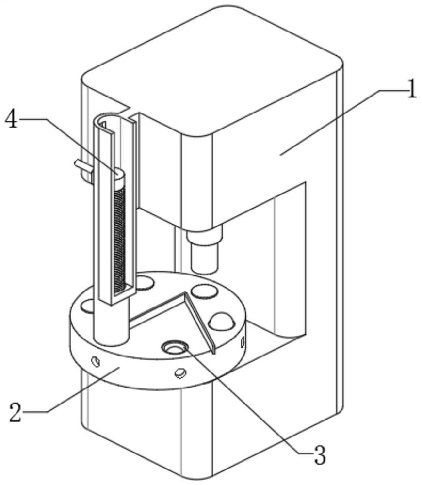
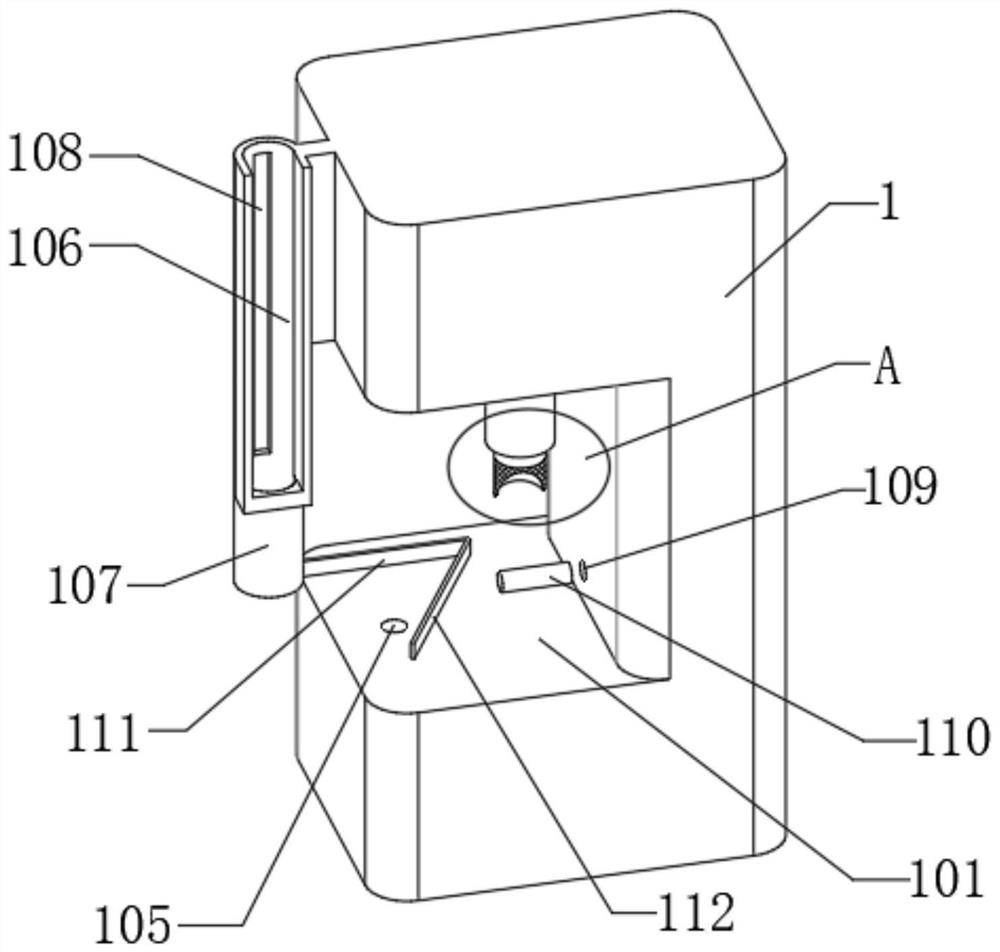
[0034] The embodiment of the present invention discloses a high-speed feeder for a punching machine, which includes a punching machine body 1, a turntable 2, a support ring 3, a pressing block 4 and a spring 5:

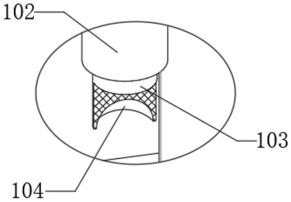
[0035] According to attached figure 1 , 2 As shown in and 3, a stamping chamber 101 is provided on the front of the punch body 1, and both sides of the stamping chamber 101 are connected to the punch body 1. A hydraulic cylinder 102 is installed on the upper surface of the stamping chamber 101, and the hydraulic cylinder 102 is arranged near the punching chamber. The position on the back of the chamber 101, the hydraulic cylinder 102 is slidably connected with the piston stamping rod 103, and the lower surface of the piston stamping rod 103 is provided with a hemispherical groove 104, starting the stamping chamber 101 can drive the hydraulic cylinder 102 to move up and down, and the stamping chamber 101 is controlled Under the command of the device, it reciprocates u...


PUM


Abstract

The invention discloses a high-speed feeding machine for a punching machine, and relates to the field of machining. The high-speed feeding machine for the punching machine comprises a punching machine body, a turntable, supporting rings, a pressing block and a spring, wherein the punching machine body is provided with a punching cavity, a hydraulic cylinder is mounted in the punching cavity, a piston punching rod is slidably connected into the hydraulic cylinder, a hemispherical groove is formed in the piston punching rod, a U-shaped barrel is fixedly connected to the punching machine body, the turntable is rotationally connected into the punching cavity, a plurality of mounting holes are formed in the turntable, connecting rods are fixedly connected to the mounting holes, hemispheres are fixedly connected to the connecting rods, the supporting rings are slidably connected into the hemispheres, mounting rings are fixedly connected to the supporting rings, the pressing block is slidably connected into the U-shaped barrel, and the mounting rod is movably sleeved with the spring. According to the high-speed feeding machine for the punching machine, the punching efficiency of metal wafers can be improved, semi-automatic feeding is achieved, a user does not need to hold the metal wafers to be placed below the piston punching rod, and the personal safety of the user is guaranteed.

Description

technical field [0001] The invention relates to the technical field of mechanical processing, in particular to a high-speed feeder for punching machines. Background technique [0002] As a stamping press, the punching machine can process the plate into the desired shape through a mold with no shape. Compared with traditional mechanical processing, it has the advantages of saving materials, energy and high efficiency. [0003] The punch press in the prior art has the following disadvantages. When the metal disc is processed by the punch press, in the process of using the punch press, the user generally puts the metal disc on the stamping die, and then the hydraulically powered stamping rod Press down to stamp the metal disc, and then the stamping rod rises, and the user can take the stamped metal disc from the mold before placing the next metal disc, so the manual feeding speed is very slow, and the stamping process The efficiency is low, and most of the hydraulically powere...

Claims


Application Information

Patent Timeline
IPC IPC(8): B21D22/08B21D43/14B21D43/24B21D45/04
CPCB21D22/08B21D43/14B21D43/24B21D45/04
Inventor 梁瑞庭赵永薛生利绍学章
Owner 广东红荔枝新材料科技有限公司
Learn More