Automatic film wrapping machine for yarn roll

A coating machine and yarn ball technology, applied in the field of yarn ball automatic coating machine, can solve the problems of increasing labor intensity and low efficiency of workers, and achieve the effects of improving coating efficiency, convenient operation, and reducing labor intensity

Active Publication Date: 2022-02-25
ZHONGQI CHANGXING LUOYANG ELECTROMECHANICAL EQUIP ENG
View PDF6 Cites 1 Cited by
  • Summary
  • Abstract
  • Description
  • Claims
  • Application Information

AI Technical Summary

Problems solved by technology

[0003] When wrapping and packaging the finished glass fiber, the glass fiber is input by two butt-connected conveyor belts, and a manual wrapping machine is placed between the two conveyor belts. Completing the coating operation is not only inefficient, but also increases the labor intensity of workers

Method used


Image

  • Automatic film wrapping machine for yarn roll
  • Automatic film wrapping machine for yarn roll
  • Automatic film wrapping machine for yarn roll

Examples


Embodiment 1

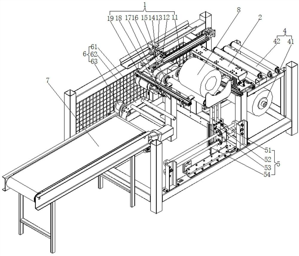
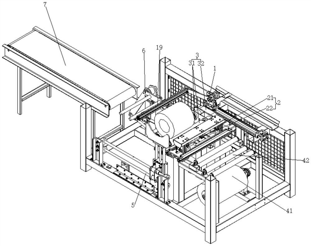
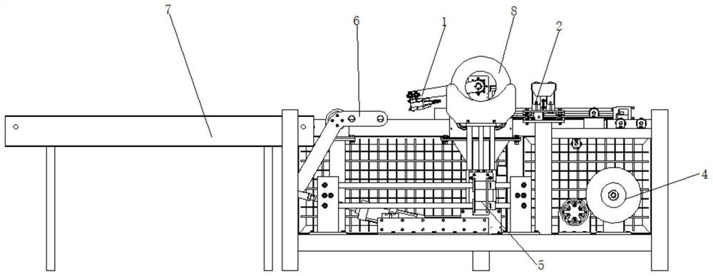
[0025] Example 1: See Figure 1-3 , the present invention provides a technical solution: an automatic yarn wrapping machine, comprising:

[0026] Laminating mechanism 2, used to compress the drawn film and carry out

[0027] Cut off, film lamination mechanism 2 comprises compression cylinder 21 and film cutting cylinder 22, the quantity of compression cylinder 21 is two groups, the quantity of film cutting cylinder 22 is one group, two groups of compression cylinders 21 are respectively arranged on cutting film cylinder 22 The two sides of film cutting cylinder 22 and compression cylinder 21 are arranged in two rows, and each row is two compression cylinders 21 and one film cutting cylinder 22;

[0028] The upper film mechanism 4 is arranged on one side of the lamination mechanism 2, and is used to place the film and control the tightness of the film. The upper film mechanism 4 includes a driving roller 41 and an upper film roller 42, and the driving roller 41 is arranged on ...

Embodiment 2

[0035]Embodiment 2: The difference from Embodiment 1 is that the film taking mechanism 1 also includes a mounting plate 17 and fixing bolts 18, the mounting plate 17 is connected with the rotating plate 19 through the fixing bolts 18, and the finger cylinder 16 is arranged on the mounting plate 17 , by connecting the finger cylinder 16 with the rotating plate 19 through the fixing bolt 18, adjust the distance between two finger cylinders 16 according to the width of the film, so as to facilitate the adjustment of the suitable position for clamping the film.


PUM


Abstract

The invention discloses an automatic film wrapping machine for a yarn roll, the automatic film wrapping machine comprises a film pressing mechanism used for pressing a film led out and cutting off the film; a film feeding mechanism is arranged on one side of the film pressing mechanism and used for placing a film and controlling the tightness degree of the film, the film feeding mechanism comprises a driving roller and film feeding rollers, the driving roller is arranged below the film feeding rollers, the film is wound on the outer side face of the driving roller, one end of the driving roller is connected with a motor, the number of the film feeding rollers is at least two, and the film feeding rollers are arranged side by side and used for tensioning and flattening the film; a film wrapping mechanism is arranged on the other side of the film pressing mechanism and used for placing the yarn roll and controlling the yarn roll to rotate; a film taking mechanism is arranged on the rear side of the film wrapping mechanism and used for grabbing and turning over the film to be tightly attached to the surface of the yarn roll. According to the automatic film wrapping machine for the yarn roll, the film wrapping operation on the yarn roll can be completed in the whole process through the machine, manual intervention is not needed, the intelligent degree is improved, and the labor intensity of workers is reduced.

Description

technical field [0001] The invention relates to the technical field of glass fiber coating, in particular to an automatic yarn coating machine. Background technique [0002] Glass fiber yarn, that is, glass fiber yarn, is drawn from molten glass liquid and wound with many single fiber strands with a diameter of <24um. Since the essence of glass fiber yarn is still glass and the silk is very Slender, after forming a ball, there will be friction, collision and breakage during the transfer process, which will affect the quality and use of the product. Therefore, it is necessary to coat the finished glass fiber yarn ball with a layer of film for protection. [0003] When wrapping and packaging the finished glass fiber, the glass fiber is input by two butt-connected conveyor belts, and a manual wrapping machine is placed between the two conveyor belts. Completing the coating operation is not only inefficient, but also increases the labor intensity of workers. Contents of th...

Claims


Application Information

Patent Timeline
Patent Type & Authority Applications(China)
IPC IPC(8): B65B11/02B65B61/06
CPCB65B11/025B65B61/06
Inventor 刘峰刘浩王际魁张戎
Owner ZHONGQI CHANGXING LUOYANG ELECTROMECHANICAL EQUIP ENG
Why Eureka
Try Eureka