
A 90° flip door frame transfer flip mechanism and its application method

A technology of turning mechanism and door frame, which is applied to conveyor objects, transportation and packaging, etc., can solve the problems of large space occupation, time-consuming and labor-intensive, and large door frame volume, so as to improve work efficiency, shorten time interval, and achieve a high degree of automation. Effect

Active Publication Date: 2022-04-08
四川和乐门业有限公司 +1
View PDF12 Cites 1 Cited by
  • Summary
  • Abstract
  • Description
  • Claims
  • Application Information

AI Technical Summary

Problems solved by technology

[0003] Due to the large size and weight of the door frame, it is time-consuming and labor-intensive to use manual direct operation to turn over the door frame, and the efficiency is low; using an automatic turning mechanism to turn the door frame can reduce the labor intensity of workers and improve production efficiency, but the existing turning mechanism is used for supporting The rotating arm for turning the door frame is very long. In order to avoid interference between the rotating arm and the ground during the turning process, it is usually necessary to set the turning mechanism on a high platform or dig a deep avoidance pit on the ground to ensure the smooth progress of the turning. Not only takes up a lot of space, but also the construction is difficult and the cost is high

Method used


Image

  • A 90° flip door frame transfer flip mechanism and its application method
  • A 90° flip door frame transfer flip mechanism and its application method
  • A 90° flip door frame transfer flip mechanism and its application method

Examples


Embodiment 1

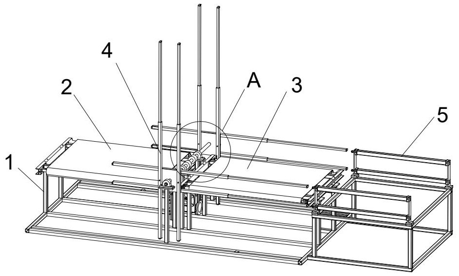
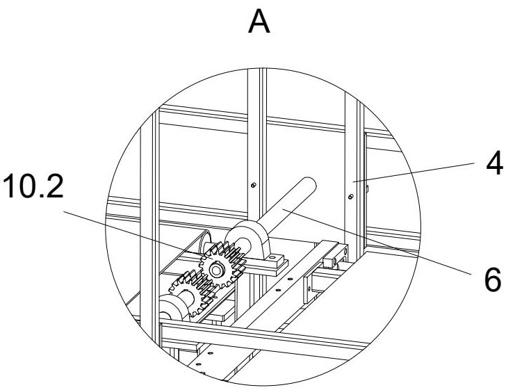
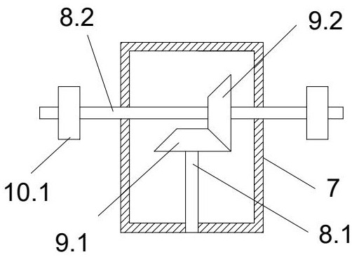
[0032] see Figure 1 to Figure 6 , the embodiment of the present invention provides a 90° flip door frame transfer and flip mechanism, including a bracket 1, a feed area 2 and a discharge area 3 arranged on the bracket 1, a flip assembly for flipping the door frame, and A driving device and a controller for driving the overturning assembly to realize overturning; the overturning assembly includes a pair of overturning units 4 that can be overturned synchronously, and the overturning units 4 are arranged on both sides of the bracket 1 and are rotationally connected with the bracket 1 through a rotating shaft 6; The overturning unit 4 includes two sets of rotating arms perpendicular to each other; each set of rotating arms includes two parallel sleeves 4.1 and a sliding tube 4.2 inside the sleeve 4.1; a spring is passed between the sliding tube 4.2 and the sleeve 4.1 Ball plunger connection; one end of the discharge area 3 of the support 1 is provided with a cylinder assembly 5 ...

Embodiment 2

[0044] Embodiment 2 provides a method for using a 90° flip door frame transfer flip mechanism, including the following steps:

[0045] S1. The first feeding: the first door frame 11 is horizontally sent into the feeding area 2 through the belt feeding mechanism. After the photoelectric sensor detects that the door frame is in place, the signal is fed back to the controller, and the controller controls the second motor in the feeding area 2. Pause; at the same time, the controller controls the cylinder assembly 5 to start, the piston rod of the cylinder stretches out, and the sliding tube 4.2 that pushes the rotating arm stretches out from the casing 4.1 to the feeding area 2;

[0046] S2, the first flip: when the cylinder reaches the maximum stroke, the sliding tube 4.2 moves into place, at this time the controller controls the cylinder assembly 5 to reset; at the same time, the first motor starts to drive the flip unit 4 to rotate 90 degrees clockwise, the first The block doo...


PUM


Abstract

The invention discloses a 90° flip door frame transfer flip mechanism and its use method. The flip mechanism includes a bracket, a feed area, a discharge area, a flip assembly, a driving device for driving the flip assembly to realize flip, and a controller; The overturning assembly includes a pair of overturning units that can be overturned synchronously. The overturning units are arranged on both sides of the bracket and are connected to the bracket through a rotating shaft. The overturning unit includes two sets of mutually perpendicular rotating arms, and each set of rotating arms includes Two parallel sleeves and the sliding tube inside the sleeve; the sliding tube and the sleeve are connected by a spring ball plunger; one end of the discharge area of ​​the bracket is set to push the sliding tube to extend from the sleeve The cylinder assembly that goes out to the feeding area; the invention solves the problem of the turning space by setting the rotating arm combined with the sliding tube and the casing, and using the driving effect of the cylinder; the 90-degree turning mode is adopted to shorten the time of feeding twice spacing, improving the flipping efficiency.

Description

technical field [0001] The invention relates to the technical field of door frame processing equipment, in particular to a 90°-turned door frame transfer printing turning mechanism and a use method thereof. Background technique [0002] Door frame transfer is a process in the process of door transfer printing. At present, the transfer printing is usually one-sided transfer printing. The door frame enters the transfer area in a horizontal state on the production line. After one side of the transfer is completed, the door frame needs to be turned over. , and then enter the transfer area again to transfer the other side. [0003] Due to the large size and weight of the door frame, it is time-consuming and labor-intensive to use manual direct operation to turn over the door frame, and the efficiency is low; using an automatic turning mechanism to turn the door frame can reduce the labor intensity of workers and improve production efficiency, but the existing turning mechanism is...

Claims


Application Information

Patent Timeline
Patent Type & Authority Patents(China)
IPC IPC(8): B65G47/252
CPCB65G47/252
Inventor 李光赋尹华春
Owner 四川和乐门业有限公司
Learn More