Foam material foaming machine

A foam material and foaming machine technology, applied in glass manufacturing equipment, glass molding, manufacturing tools, etc., can solve the problem of uncontrollable bubble size, bubble distribution uniformity, bubble number, bubble volume ratio, nano particle damage, material Performance discount and other issues, to achieve the effect of expanding the application range and application space, solving the problem of material resources, and uniform bubble size

Pending Publication Date: 2022-02-25
陈久斌
View PDF0 Cites 0 Cited by
  • Summary
  • Abstract
  • Description
  • Claims
  • Application Information

AI Technical Summary

Problems solved by technology

[0002] The existing foam material production equipment has many problems such as the inability to produce foam materials with uniform bubbles, the size of the bubbles, the uniformity of the bubble distribution, the number of bubbles, and the volume ratio of the bubbles, especially the production process of foam metal and foam glass. Backward, resulting in foam materials with excellent performance not getting their due performance, cheap production and wide application
Existing technology is even more unable to produce materials with better performance such as nano-foam materials and foam metal glass
During the production process of existing nanomaterials, the nanoparticles are damaged, which greatly reduces the performance of the materials.
The existing material production process generally lacks an important link in the material manufacturing process - material foaming. Generally, only the simple original crystalline structure of the material is used, and the material foaming, nanometerization, and soft-hard composite structure are ignored. With many advantages, it is an inevitable trend for materials to develop into foam, nano, and soft-hard combination

Method used


Image

  • Foam material foaming machine
  • Foam material foaming machine
  • Foam material foaming machine

Examples


Embodiment Construction

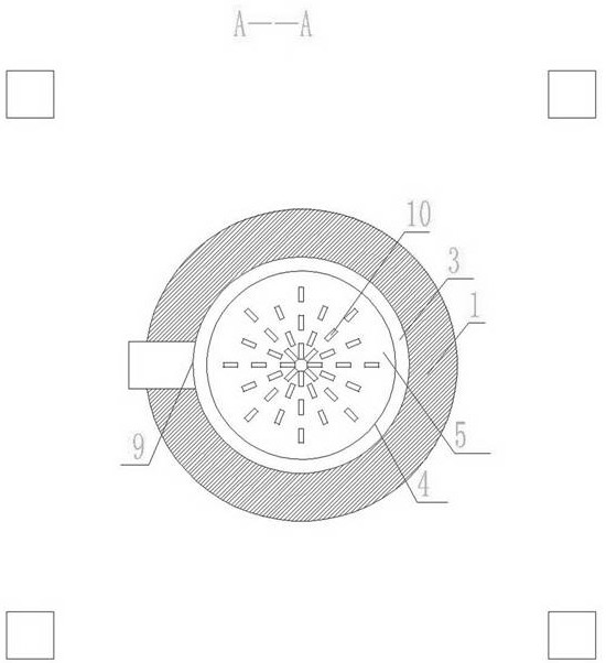
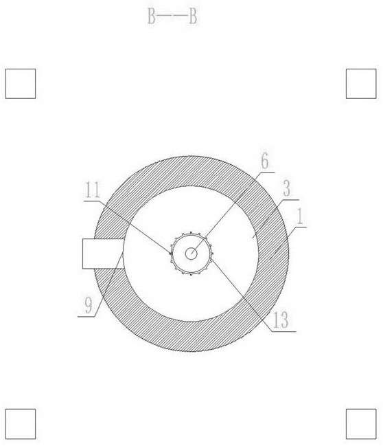
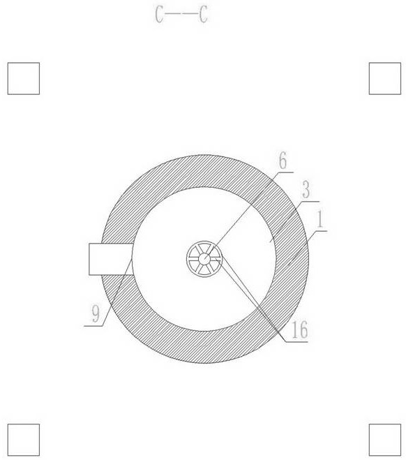
[0031] The main structure of the foam material foaming machine of the present invention includes a housing 1 and a transmission device 2, the transmission device 2 is arranged on the housing 1, a housing chamber 3 is arranged in the housing 1, a rotary grinding and foaming wheel 4 is arranged in the housing chamber 3, and the transmission The device 2 is connected with the rotary grinding and foaming wheel 4, and the rotary grinding and foaming wheel 4 is provided with a rotary grinding and foaming moving disk surface 5, and the shell cavity 3 corresponds to the rotating grinding and foaming moving disk surface 5. The middle part of the shell cavity inlet 6 is set, and the shell cavity inlet 6 is surrounded The inner wall of the housing chamber 3 is provided with a rotary grinding and foaming static disk surface 7, the rotary grinding and foaming dynamic disk surface 5 is close to the rotary grinding and foaming static disk surface 7, and a rotating grinding and foaming static d...


PUM

PropertyMeasurementUnit
particle diameteraaaaaaaaaa

Abstract

The invention relates to a foam material foaming machine, which comprises a shell and a transmission device, the transmission device is arranged on the shell, a shell cavity is formed in the shell, a rotary grinding foaming wheel is arranged in the shell cavity, the transmission device is connected with the rotary grinding foaming wheel, a rotary grinding foaming movable disc face is arranged on one face of the rotary grinding foaming wheel, and a shell cavity inlet is formed in the middle, corresponding to the rotary grinding foaming movable disc face, of the shell cavity. A rotary grinding foaming static disc surface is arranged on the inner wall of the shell cavity surrounding the inlet of the shell cavity, the rotary grinding foaming movable disc surface is close to the rotary grinding foaming static disc surface, a rotary grinding foaming cavity is arranged between the rotary grinding foaming movable disc surface and the rotary grinding foaming static disc surface, and at least one discharge hole is formed in the periphery of the shell cavity. The foam material foaming machine can produce foam materials of various materials, can replace steel, alloy, wood and the like, can change glass into a broad-spectrum material, can solve the problem of shortage of material resources, and brings a new glass civilization era.

Description

technical field [0001] The invention relates to the field of material production equipment, in particular to a foam material foaming machine. It can be used as a foam material production equipment, and can produce a variety of brand new foam materials, and can produce brand new nano foam materials (bubble particle size within 100 nanometers), micron foam materials (bubble particle size within 1 micron), millimeter foam materials (bubble particle size particle size within 1 mm), ultra-nano foam material (bubble particle size within 1 nm), etc., the foam particles of the foam material are uniform in size and arrangement, and the overall strength of the material is greatly improved. This material can replace steel, wood, plastic, rubber, Ceramics, masonry, concrete and many other materials. Background technique [0002] The existing foam material production equipment has many problems such as the inability to produce foam materials with uniform bubbles, the size of the bubbles...

Claims


Application Information

Patent Timeline
Patent Type & Authority Applications(China)
IPC IPC(8): C03B19/08
CPCC03B19/08
Inventor 陈久斌
Owner 陈久斌
Why Eureka
Try Eureka