Curvature continuous valve with adjustable flow channel
A technology with continuous curvature and flow channel, applied in valve details, valve device, valve shell structure, etc., can solve the problems of adjusting the angle of the flow channel in the valve, setting pressure adjustment dependence, not having continuous curvature, etc., to ensure the reliability of sealing , Reduce maintenance costs and ensure the effect of transmission effectiveness
- Summary
- Abstract
- Description
- Claims
- Application Information
AI Technical Summary
Problems solved by technology
Method used
Image
Examples
Embodiment 1
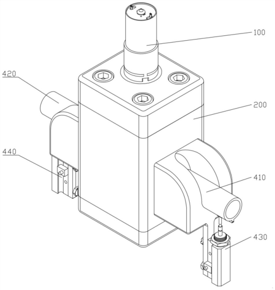
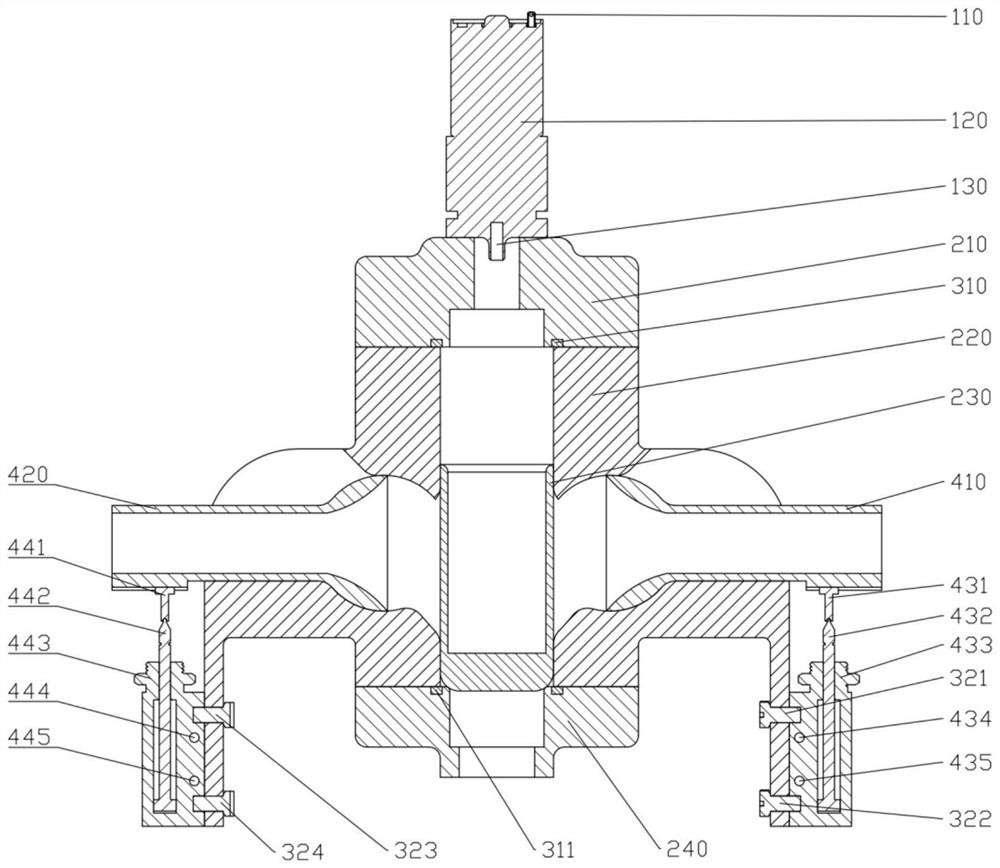
[0044] A curvature continuous valve with adjustable flow path, such as figure 1 , figure 2 As shown, it is composed of an air pump module 100 , a valve body module 200 , a connection module 300 and a channel adjustment module 400 .
[0045]In this embodiment, the air pump module 100 is composed of an air pump power interface 110 , an air pump body 120 and an air pump output hole 130 , and the air pump module is fixed above the valve top 210 through screw connections. The valve body module 200 includes a valve top 210 , a base body 220 , a valve core 230 and a valve bottom 240 . The valve top 210 is fixed above the base body 220 by bolts, and the valve bottom 240 is fixed below the base body by bolts. The connection module 300 includes an upper washer 310 , a lower washer 311 , a bolt one 321 , a bolt two 322 , a bolt three 323 , and a bolt four 324 .
[0046] In this embodiment, the flow channel adjustment module 400 includes a right flow channel 410, a left flow channel 42...
Embodiment 2
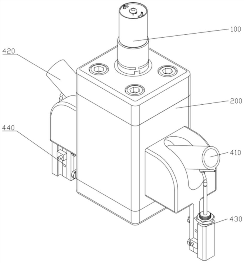
[0048] A curvature continuous valve with adjustable flow path, such as image 3 , Figure 4 As shown, the curvature continuous valve with adjustable flow path is in working state at this time. Taking the adjustment process of the right flow path 410 as an example, the technical solution of the present invention is described. The adjustment technical solution of the left flow path 420 is similar to that of the right flow path 410. I won't repeat them here.
[0049] In this embodiment, the air pump module 100 charges and deflates the valve through the air pump output hole 130 , so as to realize the preset of the set pressure. When the pressure of the fluid medium under the spool 230 exceeds the set pressure, the spool 230 moves up under the pressure, the curvature continuous valve opens, and the valve enters the working state.
[0050] At this time, the angle of the right channel can be adjusted according to the working conditions to reduce the pressure loss when the fluid med...
Embodiment 3
[0052] A curvature continuous valve with adjustable flow path, such as Figure 5 Shown is a side view of the present invention, taking the working process of the right flow channel adjustment module 430 as an example to illustrate the technical solution of the present invention, the technical solution of the left flow channel adjustment module 440 is similar to that of the right flow channel adjustment module 430, and will not be repeated here .
[0053] In this embodiment, the right cylinder rod 432 is connected to the right adjustment slider 431 through a ball joint structure. When the relative position (angle) between the right cylinder rod 432 and the right adjustment slider 431 changes, the ball joint structure ensures that the right cylinder The rod 432 is always connected with the right adjusting slider 431; the right adjusting slider 431 is connected with the right runner 410 through the right runner dovetail groove 413, forming a linear motion pair, ensuring that the ...
PUM
 Abstract
Description
Claims
Application Information
 - R&D
- Intellectual Property
- Life Sciences
- Materials
- Tech Scout
- Unparalleled Data Quality
- Higher Quality Content
- 60% Fewer Hallucinations
Browse by: Latest US Patents, China's latest patents, Technical Efficacy Thesaurus, Application Domain, Technology Topic, Popular Technical Reports.
© 2025 PatSnap. All rights reserved.Legal|Privacy policy|Modern Slavery Act Transparency Statement|Sitemap|About US| Contact US: help@patsnap.com


