Doughnut cabinet lamp
A donut and cabinet technology, which is applied in the field of small household appliances, can solve the problems of inconvenient installation, cumbersome cabinet lights, and inability to apply various scenarios, and achieves convenient installation, outstanding modeling features, light and high Effect
- Summary
- Abstract
- Description
- Claims
- Application Information
AI Technical Summary
Problems solved by technology
Method used
Image

Examples
Embodiment Construction
[0013] The donut-style cabinet light provided by the present invention will be further described in detail and completely below in conjunction with the embodiments. The embodiments described below are exemplary only for explaining the present invention and should not be construed as limiting the present invention.
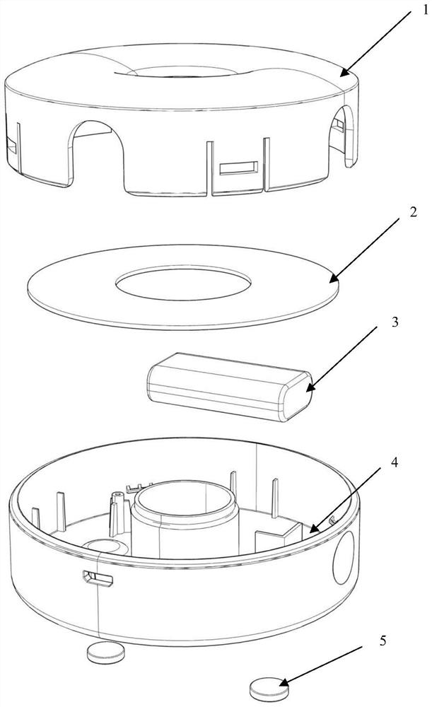
[0014] A donut style cabinet lamp, as shown in the figure, includes a lampshade 1, a printed circuit board 2, a lithium battery 3, a bottom cover 4, and a built-in magnet. Among them, the lithium battery and the built-in magnet are installed at the bottom inside the bottom cover.
[0015] The lampshade and the bottom cover are fixed by buckles, and the bottom cover has a limit post to ensure a stable connection between the bottom cover and the lampshade.
[0016] The printed circuit board and the bottom cover are fixed with screws. The Micro USB interface on the printed circuit board is directly drawn out through a hole on the bottom cover for power supply and ba...
PUM
 Abstract
Description
Claims
Application Information