
Novel bell-jar furnace

A bell jar furnace and a new type of technology, applied in the field of bell jar furnaces, can solve the problems of unspecified lifting parameters of scissor hydraulic lifting platform, low efficiency, high height, etc. Effect

Pending Publication Date: 2022-02-25
义乌市台荣超硬制品有限公司
View PDF1 Cites 0 Cited by
  • Summary
  • Abstract
  • Description
  • Claims
  • Application Information

AI Technical Summary

Problems solved by technology

"But it did not explain the lifting parameters of the scissor hydraulic lift table
For the furnace body of the traditional bell furnace, in order to improve the applicability to the workpiece, the lifting height of various lifting platforms generally exceeds 800 mm, which is very inconvenient to operate and low in efficiency, and the overall height of the equipment is also too high

Method used


Image

  • Novel bell-jar furnace
  • Novel bell-jar furnace
  • Novel bell-jar furnace

Examples


Embodiment 1

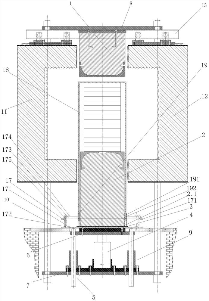
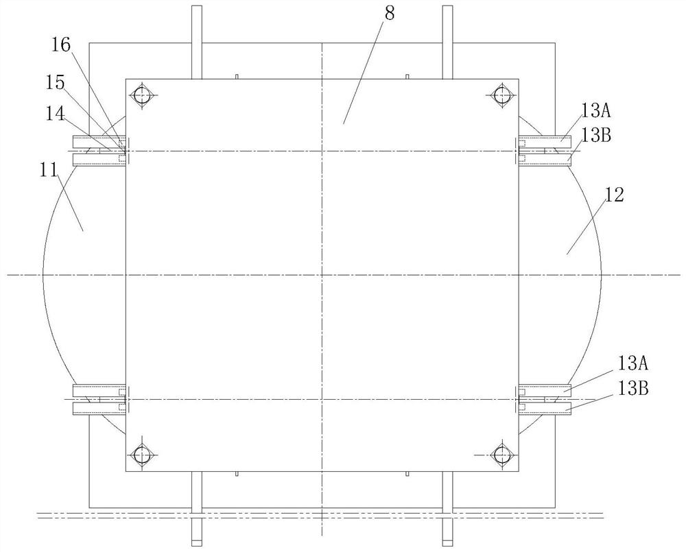
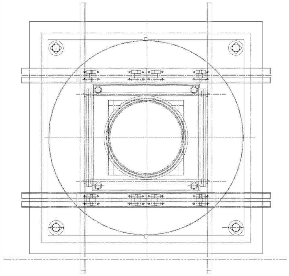
[0022] Such as figure 1 , figure 2 , image 3 As shown, the present invention includes an upper furnace 1, a lower furnace 2, a lower furnace support 3, a lifting device 4, a guide column 5, a lifting frame upper plate 6, a lifting frame lower plate 7, an upper furnace mounting plate 8, Guide post guide seat 9, column 10, left half furnace body 11, right half furnace body 12, furnace body track 13, furnace body installation frame. Described furnace body installation frame comprises hanger 14, wheel shaft 15, roller 16, lower furnace Dun level pushing mechanism 17. The outer ends of the left half furnace body 11 and the right half furnace body 12 are semi-cylindrical, and the upper and lower ends are respectively semi-circular. Lifting device 4 can be a kind of in multiple lifting devices such as hydraulic lifting device, air pressure lifting device, gear lifting device, and their structure and working principle all are known technologies, do not repeat them here;

[0023]...

Embodiment 2

[0031] The difference between the second embodiment and the first embodiment is that the main body of the furnace track 13 in the second embodiment is in a "concave" shape, and the upper ends of the front and rear side walls of the furnace track 13 are each provided with a number of connecting ears and through these connecting ears It is detachably connected with the upper furnace mounting plate 8, and the bottom of the furnace track 13 is provided with a left-right groove to form a section of the corresponding interval between the middle rail body 13A and the rail body 2 13B in Embodiment 1 for installing the furnace. body mount.

Embodiment 3

[0033] The difference between the third embodiment and the first embodiment is that the wheel track 13 and the upper furnace mounting plate 8 in the third embodiment are the same body, and the corresponding parts of the front and rear ends of the corresponding upper furnace mounting plate 8 are respectively provided with Two grooves going left and right; the upper end of the hanger 14 is located at the upper end of the upper furnace mounting plate 8, and the front and rear ends of each wheel shaft 15 are respectively provided with a roller 16 that is respectively rolled and supported on the upper furnace mounting plate 8. Preferably, the upper furnace mounting plate 8 is also detachably connected with the corresponding dust cover to prevent falling on the moving track of the rollers. The specific structural details are not repeated here because they are simple techniques.


PUM


Abstract

A novel bell-type furnace comprises an upper furnace pier, a lower furnace pier, a lower furnace pier supporting plate, a lifting device, guide columns, a lifting frame upper plate, a lifting frame lower plate, an upper furnace pier mounting plate, guide column guide seats, stand columns, a left half furnace body, a right half furnace body, furnace body rails, a furnace body mounting frame and a lower furnace pier horizontal pushing mechanism. The furnace body installation frame comprises a hanging bracket, a wheel shaft and idler wheels. And the upper end of the furnace body rail is fixedly connected with the upper furnace pier mounting plate. The upper ends of the left half furnace body and the right half furnace body are fixedly connected with the lower ends of the hanging brackets, the upper ends of the hanging brackets are fixedly connected with the corresponding wheel shafts, the corresponding idler wheels are connected with the wheel shafts, and the wheel rollers are supported on the furnace body guide rails in a rolling mode. And the lower furnace pier horizontal pushing mechanism comprises a guide rail, a roller mounting shaft, a mounting shaft connecting piece and a bearing plate. The shaft rollers are supported on the guide rails in a rolling mode. And a lower pier plate at the lower end of the lower pier is placed on the bearing plate. According to the novel bell-type furnace, the lifting of the lifting table and the overall height of equipment are greatly reduced, the overall operation efficiency is high, and the equipment is easier to maintain.

Description

technical field [0001] The invention relates to a sintering device, in particular to a bell furnace. Background technique [0002] The bell furnace is a kind of equipment that is very suitable for the sintering production of superhard material products. Application number 201920641142.4, authorized announcement number CN 210242363 U, and a Chinese utility model patent document titled "A Bell Furnace with a Movable Sintering Platform" disclose a bell furnace: "comprising a furnace body, fixed on The support seat at the bottom of the furnace body, the scissor hydraulic lifting platform fixedly installed in the center of the support seat, and the setting table placed on the scissor hydraulic lifting platform and able to cooperate with the furnace body feeding port, the outer side of the lower end of the scissor hydraulic lifting platform There is also a return-type pressure bearing plate, the four corners of the bottom end of the return-type pressure bearing plate are respecti...

Claims


Application Information

Patent Timeline
Patent Type & Authority Applications(China)
IPC IPC(8): F27B11/00F27D99/00
CPCF27B11/00F27D99/00F27D2099/0098
Inventor 陈政伟
Owner 义乌市台荣超硬制品有限公司
Learn More