Hanging disc positioning method and hanging disc hanging method
A positioning method and a positioning surface technology, which are applied to measuring devices, instruments, optical devices, etc., can solve problems such as mounting failures and multiple mountings
Pending Publication Date: 2022-02-25
BEIJING SHEENLINE GRP CO LTD
0 Cites 0 Cited by
AI-Extracted Technical Summary
Problems solved by technology
In the above process, it is an important prerequisite for the subsequent flaw detection to accurately connect the mounting plate to the adapter. However, the current positioning method of mou...
Method used
[0055] In some embodiments, the articulated plate 210 and the moving part 300 are installed on the flaw detection equipment 200, the distance measuring part 410 and the visual positioning part 420 are installed on the moving part 300, and the moving part 300 is set independently of the articulated plate 210. Specifically, both the distance measuring part 410 and the visual positioning part 420 are installed at the end of the kinematic joint of the moving part 300, and the installation orientation of the two is the same. In S300, the moving part 300 can simultaneously drive the two to rotate to face the adapter 110 end face b, higher positioning efficiency. In S700 , the moving part 300 grabs the hooking tray 210 installed on the fe...
Abstract
The invention relates to a hanging disc positioning method and a hanging disc hanging method. The hanging disc positioning method comprises the steps that a distance measuring piece is driven by a moving piece to move to at least three positions in sequence, the distance measuring piece obtains the distance between the distance measuring piece and the end face of an adapter at all the positions, a reference plane is defined by all the positions, the direction perpendicular to the positioning face of a visual positioning piece serves as the z direction, the reference plane is perpendicular to the z direction, and the measuring direction of the distance measuring piece is the z direction; if the distances measured at all the positions are not equal, an included angle alpha between the reference plane and the end face of the adapter is calculated according to the distances obtained at three positions and the side length of a triangle defined by the three positions; the visual positioning piece and the distance measuring piece are driven by the moving piece to rotate by alpha; the distance between the distance measuring piece and the end face of the adapter is obtained; an image of the end face of the adapter is acquired through the visual positioning piece; and the acquired data are compared with the position data of the hanging disc. The positioning method enables positioning to be more accurate.
Application Domain
Using optical means
Technology Topic
Mechanical engineeringDistance measurement +4
Image
Examples
- Experimental program(1)
Example Embodiment
[0032] In order to make the above objects, features, and advantages of the present invention, the specific embodiments of the present invention will be described in detail below with reference to the accompanying drawings. Many specific details are set forth in the following description to fully understand the invention. However, the present invention can be implemented in many different fails thereof, and those skilled in the art can do similar improvements without departing from the connotation of the present invention, and thus the present invention is not limited by the specific embodiments disclosed below.
[0033] In the description of the present invention, it is to be understood that the terms "center", "longitudinal", "horizontal", "length", "width", "thickness", "upper", "under", "front", " After "," left "," right "," vertical "," horizontal "," top "," bottom "," internal "," outside "," clockwise "," counterclock "," axial " , "Radial", "circumferential" or the like, is based on the orientation or positional relationship shown in the drawings, is merely described in order to facilitate the description of the present invention, rather than indicating or implying means of means or The components must have specific orientation, constructed and operated in specific orientation, and thus is not to be construed as limiting the invention.
[0034] Moreover, the term "first", "second" is used only for the purpose of describing, and cannot be understood as an indication or implies a relative importance or implicitting the number of indicated techniques. Thus, the features of "first", "second" are defined, and at least one of the features may be indicated or implicitly. In the description of the invention, the meaning of "plurality" is at least two, such as two, three, etc., unless otherwise specifically defined.
[0035] In the present invention, the terms "mount", "connected", "linked", "fixed", such as the term "mount", "connected", "linked", "fixed", may be a fixed connection, or a detachable connection may be a fixed connection. One integration; may be mechanical connection, or electrical connection; may be directly connected, or indirectly connected by an intermediate medium, which can be in connection with two components or two components, unless otherwise clear Limited. The specific meaning of the above terms in the present invention can be understood in terms of specific cases.
[0036] In the present invention, unless otherwise expressly specified and defined, the first feature may be in direct contact between the first and second features, or the first and second features indirect through the intermediate medium. touch. Moreover, the first feature "above", "above", and "upper", but the first feature is above or obliquely above the second feature, or only means that the first feature level height is higher than the second feature. The first feature is in the second feature "under" "lower" and "below" may be that the first feature is below the second feature or obliquely below, or only the first feature level height is less than the second feature.
[0037]It should be noted that when the element is referred to as "fixed to" or "set" another element, it can be directly in another element or may also exist. When an element is considered to be "connected" another element, it can be directly connected to another element or may exist at the same time. The term "vertical", "horizontal", "upper", "lower", "left", "right", and similar expressions are not shown in the purpose of illustration.
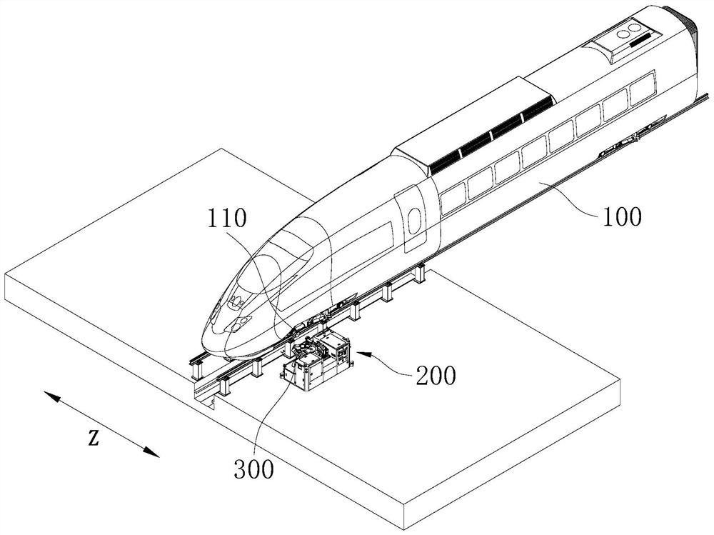
[0038] See Figure 1 to 3 The mounting disk positioning method provided by an embodiment of the present invention includes the following steps:
[0039] S120 moves the distance measuring member 410 by the moving parts 300 to at least three positions, and the distance measuring member 410 acquires the spacing of the end surface B of the adapter 110, respectively, and each position defines the reference plane A to be perpendicular to the visual positioning member. The direction of the positioning surface of 420 is the Z direction, and the reference plane A is perpendicular to the Z direction, and the measurement direction of the measurement member 410 is the Z direction;
[0040] If the S200 is not equal to the spacing of each position, the S200 is not equal to the equal distance, and the angle α of the end surface B of the reference plane A and the adapter 110 is calculated according to the spacing of the three positions, and the three positions defined.
[0041] S300 drives the visual positioning member 420 through the moving parts 300 to rotate α from the distance measuring member 410 to cause the positioning surface to be parallel to the end surface B of the adapter 110, and the measurement direction of the distance measurement member 410 is perpendicular to the end surface B of the adapter 110;
[0042] The S400 acquires the pitch of the end surface B of the adapter 110 by distance measuring member 410;
[0043] The S500 acquires the image of the end surface B of the adapter 110 through the visual positioning member 420;
[0044] The S600 compares the data acquired in the S400, S500 and the angle α acquired in S200 with the position data of the mounting disk 210 to obtain the relative position of the adapter 110 and the mount 210.
[0045] Specifically, the moving member 300 can be a robotic arm having a moving and rotational degree of freedom, and the distance measuring member 410 can be a member such as a laser sensor or a range finder or the like, and the visual positioning member 420 can be photographed for a camera or a camera. Functional components. The positioning surface of the visual positioning member 420 is the end surface of the photographing lens. The measurement direction of the distance measurement member 410 is the direction of the laser light, that is, the direction perpendicular to the end surface of the laser emission component. If the measurement direction of the distance measuring member 410 is perpendicular to the positioning surface of the visual positioning member 420, it is considered that the orientation of the visual positioning member 420 is the same as the orientation of the distance measuring member 410.
[0046] In this embodiment, the distance measuring member 410 is driven by the moving member 300 to at least three locations to measure the pitch of the adapter 110, and the respective positions of the distance measurement 410 are defined by the reference plane A. In the direction of the positioning surface perpendicular to the visual positioning member 420, the reference plane A needs to be perpendicular to the Z direction, i.e., the respective positions of the distance measuring member 410 are the same as the coordinates in the Z direction; while the measuring member 410 The measurement direction is in the Z direction, i.e., the orientation of the visual positioning member 420 is the same as the orientation of the distance measuring member 410. There is two orientations in the X direction and the Y direction, x, y, and z in the reference plane A. If the distance measuring member 410 measured at each position is not equal, the visual positioning member 420 and the distance measuring member 410 are not positive to the end surface B of the adapter 110, and the reference plane A and the end surface B of the reference plane A and the adapter 110 have an angle between the end surface B. . If there is an angle, it is necessary to calculate according to the spacing acquired in three positions (respectively a position, B position, C position), and the edge length of the triangular ABC defined in these three positions, to obtain the reference plane A and The angle α of the end surface B of the adapter 110. After the angle α can be obtained, the visual positioning member 420 can be rotated from the distance measuring member 410 by the moving parts 300 to rotate the visual positioning member 420 and the distance measuring member 410 to the end surface B of the adapter 110, thereby ensuring vision The data acquired by the positioning member 420 and the distance measuring member 410 is accurate and is not deviated by the existence of an angle. The image of the end surface B of the adapter 110 is then acquired by the visual positioning member 420, so that the coordinates of the end surface of the adapter 110 in the X direction and the Y direction are thus known; the spacing of the end surface of the adapter 110 is obtained by the distance measuring member 410, so that the adapter 110 is obtained. The coordinates of the end face in the z direction. Since the hosing disk 210 is known to the position of the moving member 300, i.e., the position data of the mounting disk 210 in the coordinate system of the moving member 300 is known, and the coordinates of the three directions of X, Y, Z in the end surface of the adapter 110 in the end surface of the adapter 110 are known. After that, the relative positions of the hanging disk 210 and the adapter 110 are obtained in conjunction, thereby completing the positioning. In the above-described positioning method, the visual positioning member 420 of the positioning is adjusted to the orientation of the distance measuring member 410, ensuring that the two face toward the end surface of the adapter 110, and can be used to exclude due to the existence angle. When the relative position is acquired, in addition to the distance of the hanging disk 210 and the adapter 110 on the three directions of the X, Y, Z, the angle α of the end surface of the adapter 110 is also considered, thereby relatively accurate It is learned that the opposing position of the hanging disk 210 and the adapter 110 is obtained, and the mounting disk 210 can be quickly and accurately histed to the adapter 110 after the positioning end, and the mount efficiency is improved.
[0047] In the above embodiment, if the distance measuring member 410 measured at each position is not equal, the visual positioning member 420 and the distance measuring member 410 are not positive to the end face B, the reference plane A and the adapter 110. There is an angle between the end surface B. Conversely, if the distance measuring member 410 measured at each position, the visual positioning member 420 is described in parallel to the end surface B of the distance measuring member 410 to the adapter 110, the reference plane A and the adapter 110. At this time, the conventional positioning method is directly used, and the image of the end surface B of the adapter 110 is taken directly by the visual positioning member 420, and the processor extracts the end surface B of the adapter 110 in the X direction and the Y direction, and measures according to the distance measurement 410 The spacing of the obtained pitch extracts the position of the end surface B of the adapter 110 in the Z direction, and the position of the mount 210 can obtain the two relative positions.
[0048] In S120, the distance measuring member 410 is moved to at least three positions by the moving parts 300, and the distance measuring member 410 acquires the pitch of the end surface B of the adapter 110, respectively, and each position defines the reference plane A. Since the three points can define a plane, the distance measurement member 410 needs to be measured at three positions to obtain a reference plane A. In the following embodiments, three locations will be described as an example. Of course, the distance measuring member 410 moves to three or more positions in the moving member 300, for example, by moving the distance measuring member 410 by the moving parts 300 to four positions, in these four positions, optional three The position is limited to the reference plane a. Of course, whether moving to several locations, it is necessary to ensure that the values in the Z direction are constant, and the reference plane A which can be defined is perpendicular to the Z direction, that is, the reference plane A is parallel to the positioning surface of the visual positioning member 420. Therefore, it is considered that the distance measuring member 410 moves to at least three positions in the XY plane under the moving member 300 and performs ranging.
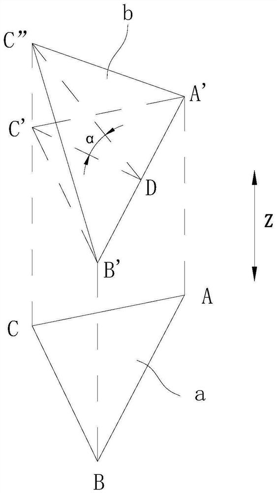
[0049] In S200, if the spacing measured at each position is not equal, according to the spacing obtained in three positions, the angle of the end surface B and the adapter 110 of the adapter 110 is calculated according to the spacing of the three positions, and the three positions defined. alpha. Specifically, in image 3 In the middle, the auxiliary line A'B ', B'C', A'c 'is made to enclose a triangle a'b'c', triangle a'b'c 'is parallel to triangles ABC, and AA' is vertical. The reference plane A is defined in triangular ABC. The angle of the end surface B of the reference plane A and the adapter 110 is the angle of the triangular a'b'c 'and the end surface B of the adapter 110. Since the distance measuring member 410 is driven by the moving member 300, it is sequentially moved to the three positions, and therefore, the processor reads the data of the moving trajectory of the moving parts 300 to know the length of each move, that is, triangular ABC The side length of the three sides of the middle, thus knowing the three sides of the triangle a'b'c '. When the three sides of the triangle are known, according to the cosine seal, it can be calculated to calculate the cell value of ∠C'B'A ', the length of the side C'B' length, is the length of the high line C'd. The length of the pitch Cc obtained by the distance measuring member 410 in position C is subjected to the length of the pitch Bb 'acquired at position B, ie the length of C'c "can be obtained. In triangular DC'c ", according to C'c" length and C'd length of C'd can calculate the positive cut values of ∠C'B'A ', so that ∠C'B'A' is α size.
[0050] Preferably, in some embodiments, the triangular triangle defined in the S200 is an equilateral triangle. That is, the triangular A'B'c 'and triangle ABC are equilateral triangles. Therefore, when calculating the length of the high line C'd, it can be directly known that the ∠C'B'A 'size is 60 °, and there is no need to pass the cosine theorem, the calculation process is easier, the calculation speed is faster, and the positioning efficiency is higher.
[0051] Preferably, in some embodiments, S410 is further included between S400 and S500: In S400, if the distance measuring member 410 acquired and the spacing between the end surface B of the adapter 110 is not equal, the moving parts 300 The z direction moves the distance measuring member 410 and the visual positioning member 420 until the spacing of the end surface B of the adapter 110 acquired by the distance measuring member 410 is equal to the preset spacing. Specifically, the preset spacing is an optimal spacing set in advance. At the preset spacing, the visual positioning member 420 can obtain the optimal shooting field, when shooting at the optimal field of view, the sharpness of the return image is The accuracy is better, which is conducive to increasing the positioning accuracy. Therefore, when the visual positioning member 420 is rotated from the distance measuring member 410 by the moving parts 300, the visual positioning member 420 is rotated to the distance measuring member 410 to the end surface B of the adapter 110, and again by distance from the measurement member 410, If the measured pitch is not equal to the preset spacing, the moving parts 300 drives the visual positioning member 420 and the distance measuring member 410 move in the Z direction, the moving distance is the difference between the measured spacing and the preset spacing. With this step, you can guarantee the optimal shooting field when the S500 is photographed, thereby increasing the positioning accuracy.
[0052] Preferably, in some embodiments, the S110 is further included in S120: the image of the end surface B of the adapter 110 is acquired by the visual positioning member 420 to define the motion range of the distance measuring member 410 in S120. Specifically, before S120, the image of the end surface B of the adapter 110 is first obtained by the visual positioning member 420, the processor extracts the center hole of the end face of the adapter 110 in the X direction and the Y direction, based on this substantially determines the adapter 110. The end face is in the XY plane, thereby delineates the rough range of the three positions of the distance measuring member 410 to the three positions of A, B, C, ensuring that the distance measuring member 410 is in the z direction when the distance measuring member 410 is in the z direction. The projection can be located within the end surface range of the adapter 110, thereby ensuring that the distance measuring member 410 emitted in the three positions of the A, B, and C can be played within the end face of the adapter 110, that is, the distance measuring member 410 is in A, B, C can successfully measure the spacing. If the distance from the end surface of the adapter 110 and the adapter 110 is farther away by the center hole of the adapter 110, the distance measuring member 410 can be made when the distance measuring member 410 is moved by the moving parts 300. The three ranging points are as close as possible to the central hole of the end faces of the adapter 110 in the X direction to avoid successful ranging.
[0053]In some embodiments, the mount method includes a mount positioning method in any of the present embodiments, and further includes S700 after S600: The moving member 300 drives the mount 210 to move and rotate according to the relative position obtained in S600. Until hooks to the adapter 110. Specifically, when the relative position of the adapter 110 and the mounting disk 210 is obtained according to the aforementioned positioning method, the mounting disk 210 can be moved and rotated by the moving parts 300 until the end face central hole alignment adapter 110 The central center hole and completes the hook. Since the visual positioning member 420 for positioning is adjusted to the orientation of the distance measuring member 410, it is possible to eliminate the presence of the presence ornament of the orientation of the direction of the adapter 110. The positioning error generated by the angle, in addition to the relative position, in addition to the distance from the three directions and the adapter 110 end faces in X, Y, Z, the angle α of the end surface of the adapter 110 is considered, thereby More accurately known the relative position of the hanging pickup 210 and the end surface of the adapter 110, the mounting disk 210 can be quickly and accurately histed to the adapter 110 after the positioning end, and the mount efficiency is improved.
[0054] Preferably, in some embodiments, in S700, the inductor sensing the mount 210 is hung by the inductor induction disk 210 by the inductor induction disk 210 or adapter 110. If the sensor detects an abnormality, the mount failed, the operator checks the reason, and re-hook the fault. Specifically, a proximity sensor can be disposed adjacent the end surface of the mount 210, and it is judged by the proximity sensor to be hung in place. Alternatively, a proximity sensor can be provided near the end surface of the adapter 110.
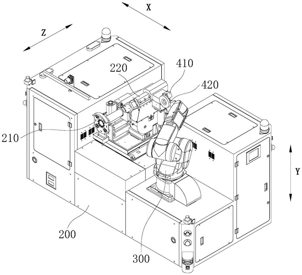
[0055] In some embodiments, both the mounting disk 210 and the moving member 300 are mounted to the flawless device 200, and both the distance measuring member 410 and the visual positioning member 420 are mounted on the moving member 300, and the moving member 300 is set independently of the mount 210. Specifically, both the distance measuring member 410 and the visual positioning member 420 are mounted on the end of the moving joint of the moving member 300, and the mounting of the two is the same, in S300, the moving member 300 can simultaneously drive the two to the front of the adapter. 110 end face B, the positioning efficiency is higher. In S700, the moving member 300 implements the gripping of the mount 210 mounted on the feed mechanism 220 by grabbing the feed mechanism 220. When the moving member 300 drives the feed mechanism 220, the mount 210 synchronously moves. Of course, if the positioning efficiency is not considered, the distance measuring member 410 and the visual positioning member 420 may not be mounted to the moving member 300, and the distance measuring member 410 and the visual positioning member 420 may be placed in two positions on the detection device 200, respectively. The orientation of the two is the same. In S300, the moving member 300 can capture and drive the distance measuring member 410 to rotate, release it, and then grab and drive the visual positioning member 420 to rotate.
[0056] In other embodiments, the moving member 300 is mounted to the detection device 200, the distance measuring plate 210, and the distance measuring member 410 and the visual positioning member 420 are mounted to the moving member 300. Specifically, the feed mechanism 220 mounted on the mounting disk 210 is mounted on the end of the moving joint of the moving member 300; the distance measuring member 410 and the visual positioning member 420 are also mounted on the end of the moving joint of the moving member 300, and both The installation is the same. As such, after S600, S700 can be performed directly, i.e., after the positioning is completed, the feed mechanism 220 can be moved directly by the moving parts 300, thereby hosing the mount 210 mounted on the feed mechanism 220 to the adapter 110, saving The steps of the feed mechanism 220 can be further improved by moving parts 300, and the hook efficiency can be further improved. The following examples are shown in the drawings, and the following embodiments will still be described as the reference.
[0057] In some embodiments, S010 is further included before S110: The flawless device 200 drives the mount 210 to move to the coordinates in the Z direction to reach the preset range. Specifically, before the hook, the detection device 200 is far from the locomotive 100, and therefore, it is necessary to drive the mounting disk 210 near the adapter 110 to the closer range by the flawless device 200 to cause the moving member 300 to move the disk 210 motion. The path is shorter, and the requirements for the mobile part 300 are lower. Specifically, the main body portion of the flawing apparatus 200 is automatically guided by AVG (Automated Guided Vehicle). The equipment is laid in the equipment to lay a magnetic strip and establish the electronic map of the locomotive vehicle, which is stored in the processor and AVG automatically guided the transport vehicle. The processor automatically guides the transport vehicle to the AVG automatically guided the transport vehicle to the AVG. The AVG automatic guidance transport vehicle carries the part of the mount 210 and the detection rod and walks according to the walking route task, and walks near the hollow axle to be detected. Then the end joint of the moving member 300 here is extended and a series of positioning steps are performed.
[0058] In some embodiments, S020 is further included between S010 and S110: The spacing of the end surface B of the adapter 110 is acquired by distance measuring member 410, and compared with the preset value;
[0059] If the alignment is the difference between the difference, the positioning step is performed.
[0060] If the alignment is that the difference is that the difference is not within the error range, the flawless device 200 drives the mount 210 until the alignment is the difference between the two.
[0061] Specifically, as described above, the main body portion of the flawless device 200 is AVG automatically guided the transport vehicle, and there may be a certain error when moving, and therefore, when the movement is in place, the ranging from the measuring member 410, and Contrast with the preset value. If the difference between the two is within the error range, the error is small, and there is no need to adjust the position without the need to cause an excessive impact on the subsequent positioning and the hook process; if the difference is outside the error range, the error is large, It is necessary to move through the flawless module (including the AVG Automatic Guide Transport Veh) through the body portion of the flawless device 200 (including the hook 210, the feed mechanism 220 and the detection rod, etc.) until the difference is within the error range. Thereby increasing subsequent positioning accuracy, ensuring accurate hosing.
[0062] When the mounting disk 210 is hooked to the adapter 110, the partial retest of the detective rod is driven by the feed mechanism 220, and the hollow axle is detected.
[0063] The various technical features of the above examples may perform any combination, in order to make the description, the various technical features of the above embodiments are not described, however, as long as the combination of these technical features does not have contradictions, It should be considered as the scope of this specification.
[0064] The above embodiments are merely expressed in several embodiments of the present invention, which are more specific and detailed, but are not to be construed as limiting the invention. It should be noted that in terms of one of ordinary skill in the art, several deformations and improvements can be made without departing from the concept of the present invention, which belongs to the scope of the present invention. Thus, the scope of the scope of the invention should be taken in the appended claims.
PUM


Description & Claims & Application Information
We can also present the details of the Description, Claims and Application information to help users get a comprehensive understanding of the technical details of the patent, such as background art, summary of invention, brief description of drawings, description of embodiments, and other original content. On the other hand, users can also determine the specific scope of protection of the technology through the list of claims; as well as understand the changes in the life cycle of the technology with the presentation of the patent timeline. Login to view more.