
Crankshaft stress testing device

A stress test, crankshaft technology, used in measuring devices, internal combustion engine testing, and the use of stable tension/pressure to test the strength of materials, etc.

Pending Publication Date: 2022-02-25
深圳臻宇新能源动力科技有限公司
View PDF0 Cites 0 Cited by
  • Summary
  • Abstract
  • Description
  • Claims
  • Application Information

AI Technical Summary

Problems solved by technology

Among them, the crankshaft is a rotating part during the working process. When testing the fatigue strength of the crankshaft, the lead wires are easily entangled, which has a negative impact on the test, and there is room for improvement.

Method used


Image

  • Crankshaft stress testing device
  • Crankshaft stress testing device
  • Crankshaft stress testing device

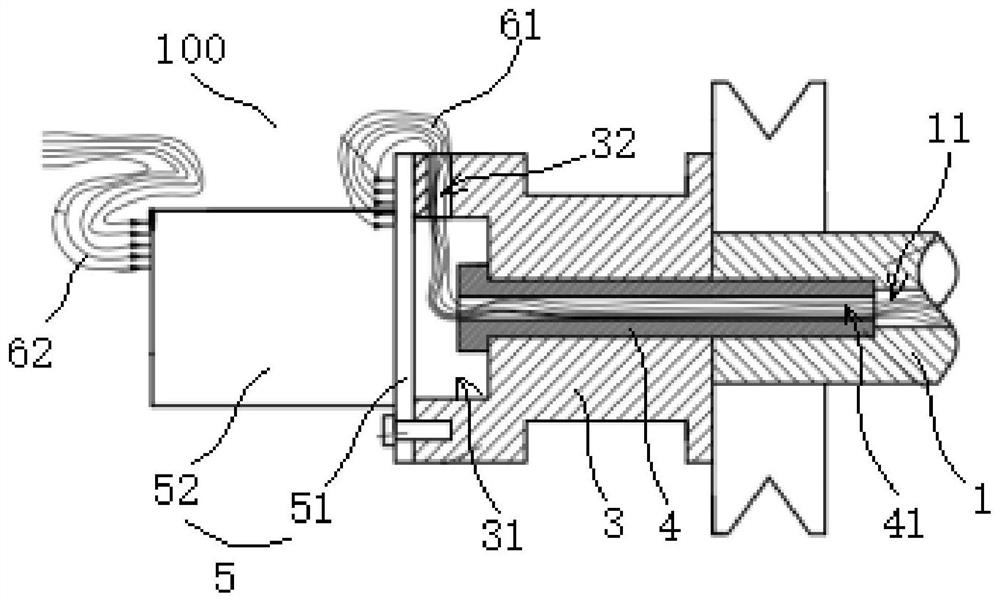
Examples


Embodiment Construction

[0023] Embodiments of the present application are described in detail below, examples of which are shown in the drawings, wherein the same or similar reference numerals denote the same or similar elements or elements having the same or similar functions throughout. The embodiments described below by referring to the figures are exemplary, and are only for explaining the present application, and should not be construed as limiting the present application.

[0024] Refer below Figure 1-Figure 3 Describe the crankshaft stress test device 100 according to the embodiment of the present application, the crankshaft stress test device 100 can realize the test of the fatigue strength of the crankshaft 1, and the problem of entanglement of the connecting wire 61 will not occur during the test process, avoiding the problem of the connection wire 61 during the test process. 61 cases of winding and breaking, to ensure the accuracy of the test.

[0025] Such as Figure 1-Figure 3 As show...


PUM


Abstract

The invention discloses a crankshaft stress testing device, and the device comprises: a crankshaft which is attached with a strain gauge; a connecting piece,wherein the connecting piece is mounted at the end part of the crankshaft; a sliding ring, wherein the sliding ring comprises a rotating part and a fixed part which are in running fit, the rotating part is connected with the connecting piece, a connecting line of the strain gauge penetrates through the crankshaft, the connecting piece is connected with the rotating part, and the fixed part is connected with an output wire harness. According to the crankshaft stress testing device, the rotating part and the fixed part of the slip ring are matched with the end part of the crankshaft, so that the situation that stress signal transmission is realized by completely adopting a wire harness is avoided, the problem of wire harness winding is avoided, the safety and reliability of the testing process are ensured, and the connecting line between the rotating part and the strain gauge is arranged in the structure in a penetrating manner, so that the accuracy of signal transmission of the connecting line is improved, and meanwhile, the problem of winding of the connecting line is effectively avoided.

Description

technical field [0001] The present application relates to the technical field of vehicle manufacturing, in particular to a crankshaft stress testing device. Background technique [0002] The crankshaft and connecting rod mechanism is the mechanism that generates and outputs power, and is the main moving part that enables the engine to realize thermal function conversion. The body is the basic skeleton of the engine, providing space for the piston to move. The piston and connecting rod are used to withstand the gas pressure, push the crankshaft to rotate and do work, and output power to the outside. Among them, the crankshaft is a rotating part during the working process. When the fatigue strength test of the crankshaft is carried out, the lead wire is very easy to go out and twisted, which has a bad influence on the test, and there is room for improvement. Contents of the invention [0003] This application aims to solve at least one of the technical problems existing in...

Claims


Application Information

Patent Timeline
IPC IPC(8): G01L1/22G01N3/08G01M15/04
CPCG01L1/22G01N3/08G01M15/04G01N2203/0075
Inventor 王奇峰
Owner 深圳臻宇新能源动力科技有限公司
Learn More