
Controllable hot melt adhesive spinning method and device

A technology of spinning device and hot-melt adhesive, applied in the direction of ejecting device, liquid ejecting device, etc., can solve the problems of easy entanglement, flashing, and large amount of glue consumption of rubber threads, saving compressed air, good sealing performance, The effect of saving glue

Inactive Publication Date: 2009-07-29
深圳金皇尚热熔胶喷涂设备有限公司
View PDF4 Cites 0 Cited by
  • Summary
  • Abstract
  • Description
  • Claims
  • Application Information

AI Technical Summary

Problems solved by technology

However, this structure makes the rubber filaments ejected from two adjacent glue spraying holes prone to entanglement, difficult to control the rubber filaments, and prone to flashes and glue flying.
[0006] There is also a spray unit group, the glue spray holes and air spray holes are arranged in parallel according to air, glue, air, glue, gas..., or two air spray holes are arranged between the glue spray holes, to a certain extent It overcomes the shortcomings of the above-mentioned technologies, but the control of the glue filament is still not very good-because the non-convergent guiding colloid flow is a passive guiding method, the gas flow needs to have sufficient pressure and speed, otherwise each gas flow It will interfere with each other, and it is still prone to overlap of flash, flying glue and glue filament, resulting in glue consumption
At the same time, due to the need for sufficient pressure and velocity of the gas flow, a considerable amount of compressed air is required, and the cost is high

Method used

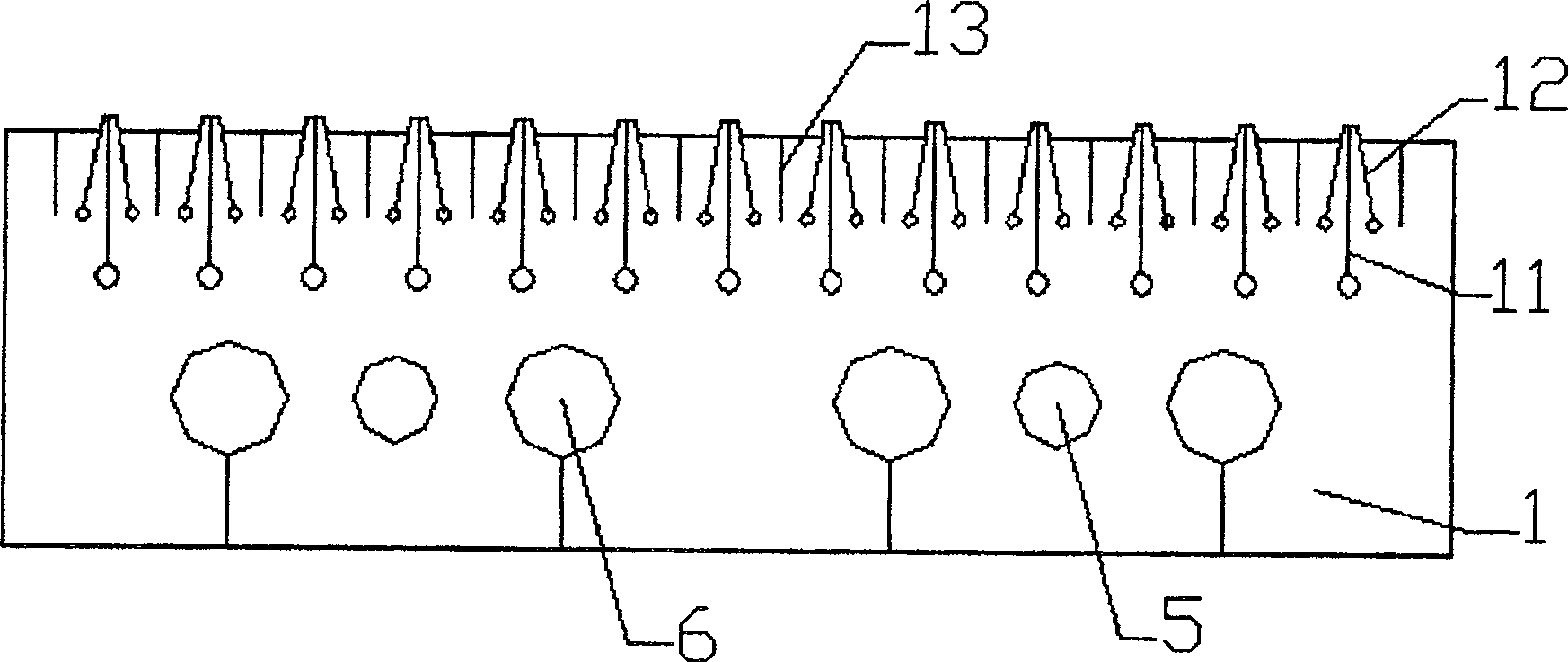
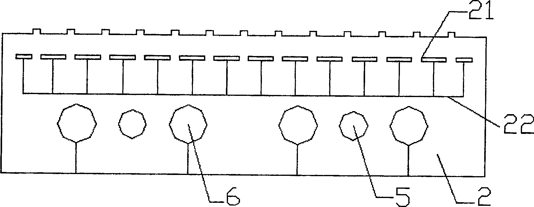

Image

  • Controllable hot melt adhesive spinning method and device
  • Controllable hot melt adhesive spinning method and device
  • Controllable hot melt adhesive spinning method and device

Examples


Embodiment Construction

[0032] The present invention will be further elaborated below according to the drawings and specific embodiments.

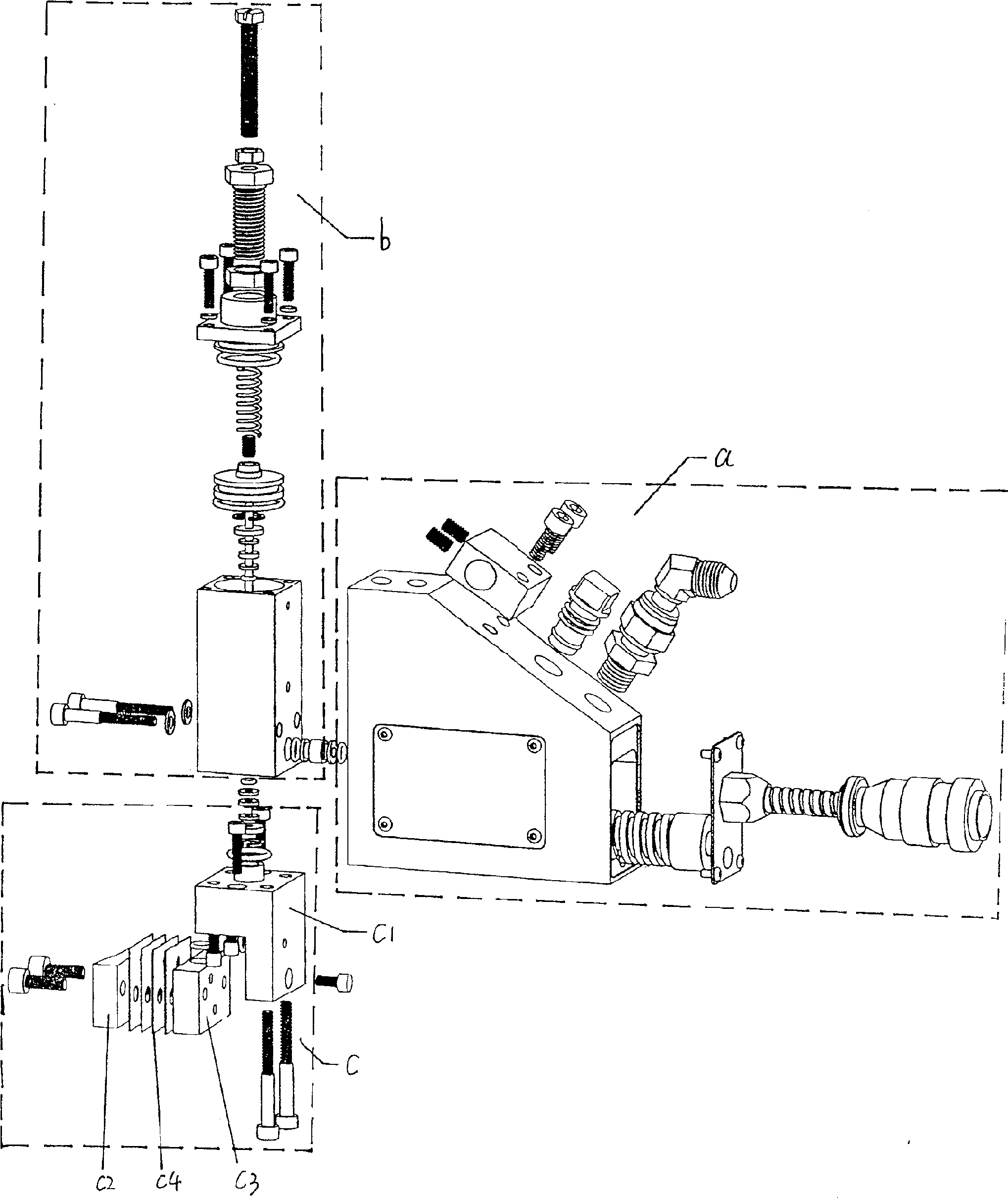
[0033] figure 1 Shown is a device for implementing the method of the present invention, a controllable hot-melt adhesive spinning device, including a heating seat a, used to heat each part of the hot-melt adhesive controllable spinning device and the hot melt adhesive and compression Air. The heating seat a also includes a heating rod, on which a spiral compressed air channel is processed to increase the heat exchange area of ​​the compressed air and increase the temperature of the compressed air.

[0034] The needle valve body b is used to control the supply of hot melt adhesive, and the pneumatically controlled hot melt adhesive flow valve controls the on-off of the glue channel to complete the intermittent coating of the sprayed glue. The needle valve body b includes a cylinder plug and a striker, etc., which can realize the action of air opening and air clo...


PUM


Abstract

The invention relates to a general melt blow molding method and a nozzle assembly for implementing the melt blow molding method, in particular to a controllable spinning method and device for hot melt adhesive. The hot melt adhesive controllable spinning method includes the following steps 101, dispersing hot melt adhesive from at least one glue channel at a first speed to form a hot melt adhesive flow; 102, using a second speed higher than the first speed from the at least one The first air passage on both sides of a glue passage disperses the gas flow to form a separated first gas flow; after the separated first gas flow converges along both sides of the hot melt glue flow to guide the hot melt glue flow, it is combined with the The hot melt adhesive streams mix to form third fluid stream filaments. The beneficial effects of the invention are: the problems of glue thread winding, flashing and flying glue will not occur, the glue thread is well controlled, the amount of glue used is greatly saved, and the cost is saved. The coating is more uniform, and the pressure of the gas flow is also small, which saves compressed air and saves costs. The sealing performance is good, and the problem of glue leakage is overcome.

Description

[0001] [Described technical field] [0002] The invention relates to a general melt blow molding method and a nozzle assembly for implementing the melt blow molding method, in particular to a controllable spinning method and device for hot melt adhesive. [Background technique] [0003] At present, with the increasingly stringent environmental requirements for products, the use of green and environmentally friendly raw materials to produce and process products has been greatly promoted in various industries. As a pollution-free and environmentally friendly adhesive, hot melt adhesive is widely used in papermaking, clothing, shoemaking, packaging, electronics and other industries. Due to the many industries involved, the strict technical requirements, and the user's requirement for accurate and efficient production at the lowest production cost, all promote the development of high-speed, low glue and gas consumption, and precise control of product quality in this industry. Unde...

Claims


Application Information

Patent Timeline
Patent Type & Authority Patents(China)
IPC IPC(8): B05B7/02B05B7/16
Inventor 侯红蕾
Owner 深圳金皇尚热熔胶喷涂设备有限公司
Learn More