
Antenna device and communication equipment thereof

A technology of antenna device and radome, which is applied in the direction of antenna support/installation device, independent antenna unit combination, antenna grounding switch structure connection, etc., which can solve the problem of low horizontal plane gain in high frequency band, low gain in low frequency band and antenna efficiency reduction , It is impossible to take into account the antenna efficiency and other issues in the antenna working frequency band, so as to avoid energy diffusion, widen the bandwidth and efficiency

Active Publication Date: 2022-02-25
SHANGHAI HAIJI INFORMATION TECH
View PDF15 Cites 0 Cited by
  • Summary
  • Abstract
  • Description
  • Claims
  • Application Information

AI Technical Summary

Problems solved by technology

[0003] At present, there have been ultra-wideband omnidirectional antennas applied to ultrashort wave communication, but there is often a situation: if the antenna radiator is too long, the high-frequency horizontal plane gain of the antenna will be very low; if the antenna radiator is too short, it will be As a result, the gain and antenna efficiency in the low frequency band will decrease rapidly
Therefore, the existing ultra-wideband omnidirectional antennas cannot broaden the operating frequency band of the antenna while taking into account the antenna efficiency

Method used


Image

  • Antenna device and communication equipment thereof
  • Antenna device and communication equipment thereof
  • Antenna device and communication equipment thereof

Examples


Embodiment Construction

[0056] In order to make the purpose, technical solution and advantages of the present application clearer, the present application will be further described in detail below in conjunction with the accompanying drawings and embodiments. It should be understood that the specific embodiments described here are only used to explain the present application, and are not intended to limit the present application.

[0057] In this application, the terms "first" and "second" are only used for descriptive purposes, and cannot be interpreted as indicating or implying relative importance or implicitly specifying the quantity of indicated technical features. Thus, the features defined as "first" and "second" may explicitly or implicitly include at least one of these features. In the description of the present application, "plurality" means at least two, for example, two, three, etc., unless otherwise specifically defined.

[0058] In this application, terms such as "installation", "connec...


PUM


Abstract

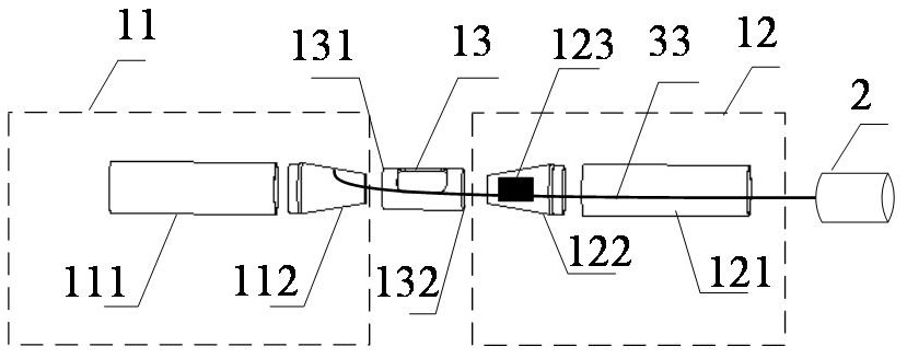
The embodiment of the invention relates to an antenna device and communication equipment thereof. The antenna device comprises at least one high-frequency radiation array element, a nonmetal first supporting assembly, a low-frequency radiation array element, a first magnetic rod and a signal output element which are arranged from top to bottom; the high-frequency radiation array element comprises a first high-frequency radiation body and a second high-frequency radiation body which are opposite array oscillators; a broadband coaxial impedance converter is arranged in the second high-frequency radiation body; the first high-frequency radiator and the second high-frequency radiator are connected through a non-metal second supporting assembly, and the opposite ends of the first high-frequency radiator and the second high-frequency radiator are circular truncated cone structure radiators with preset conicity; a first radio frequency cable of the high-frequency radiation array element is in feed connection with the low-frequency radiation array element through a first supporting assembly, and the first radio frequency cable and a second radio frequency cable of the low-frequency radiation array element are wound on the surface of a first magnetic rod and then are connected to a signal output element; and the second radio frequency cable is in feed connection with the first radio frequency cable. According to the antenna device, the antenna efficiency is considered while the working frequency band of the antenna is widened.

Description

technical field [0001] The present application relates to the technical field of antenna communication, in particular to an antenna device and communication equipment thereof. Background technique [0002] The transmission and reception of radio waves need to be completed by the antenna. As a key component of the communication front end, the importance of the antenna is self-evident. At present, in order to achieve different business needs in ultrashort wave communication, a radio station often needs to be equipped with multiple antennas. However, the carrying radio is limited by the volume of the carrier, and multiple antennas will interfere with each other, making it impossible to work at the same time, and frequent replacement of antennas is not suitable for actual use scenarios. Therefore, the development of ultra-wideband antenna technology is of great significance to ultra-short wave communication. [0003] At present, there have been ultra-wideband omnidirectional a...

Claims


Application Information

Patent Timeline
IPC IPC(8): H01Q1/36H01Q1/12H01Q1/22H01Q1/50H01Q21/30
CPCH01Q1/36H01Q1/12H01Q1/22H01Q1/50H01Q21/30H01Q21/0006
Inventor 陆超王冠君顾蔚张国伟彭超孔斌
Owner SHANGHAI HAIJI INFORMATION TECH
Learn More