Supercharge Your Innovation With Domain-Expert AI Agents!

Pole-mounted circuit breaker power taking device, circuit breaker mounting structure and power taking method

A technology of circuit breaker and power take-off device on a column, applied in circuit devices, emergency power supply arrangements, electrical components, etc., can solve the problems of long-term power failure, cumbersome composition, and reduced power supply reliability, so as to improve reliability and safety. performance, reduce the difficulty of installation, and avoid the effect of insufficient voltage

Pending Publication Date: 2022-02-25
山东汇能电气有限公司
View PDF0 Cites 0 Cited by
  • Summary
  • Abstract
  • Description
  • Claims
  • Application Information

AI Technical Summary

Problems solved by technology

[0003] The traditional pole-mounted circuit breaker is composed of three parts: the circuit breaker body, the feeder terminal and the voltage sensor. The composition is cumbersome, there are many leads, and the installation is complicated. The terminal will lose power, and the voltage transformer can only be removed and replaced. The workload is heavy, and the power must be cut off for a long time, which reduces the reliability of power supply and may even cause serious economic losses.

Method used


Image

  • Pole-mounted circuit breaker power taking device, circuit breaker mounting structure and power taking method
  • Pole-mounted circuit breaker power taking device, circuit breaker mounting structure and power taking method
  • Pole-mounted circuit breaker power taking device, circuit breaker mounting structure and power taking method

Examples


Embodiment Construction

[0032] In order to make the purpose, technical solutions and advantages of the embodiments of the present invention clearer, the technical solutions in the embodiments of the present invention will be clearly and completely described below in conjunction with the drawings in the embodiments of the present invention. Obviously, the described embodiments It is a part of embodiments of the present invention, but not all embodiments. Based on the embodiments of the present invention, all other embodiments obtained by persons of ordinary skill in the art without creative efforts fall within the protection scope of the present invention.

[0033] In addition, the term "and / or" in this article is only an association relationship describing associated objects, indicating that there may be three relationships, for example, A and / or B may indicate: A exists alone, A and B exist simultaneously, There are three cases of B alone. In addition, the character " / " in this article generally in...


PUM


Abstract

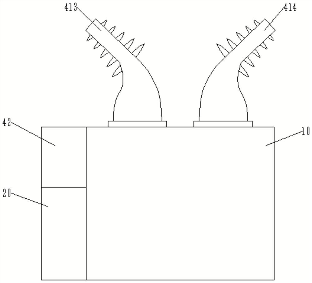
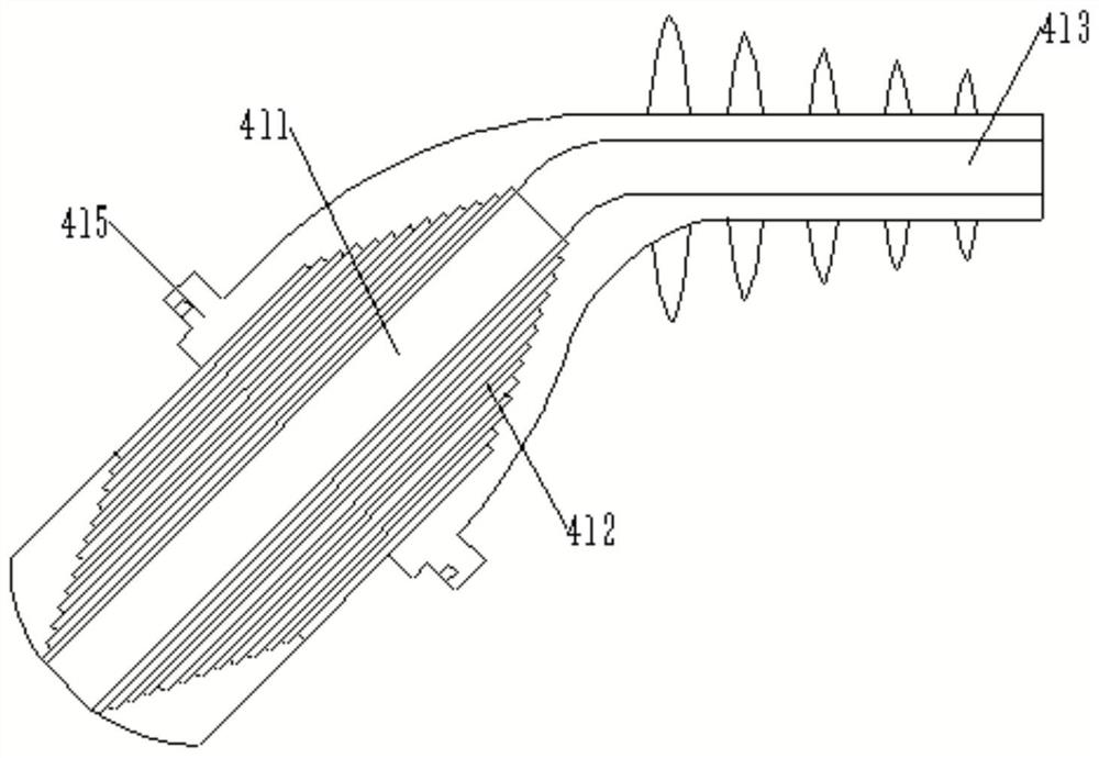
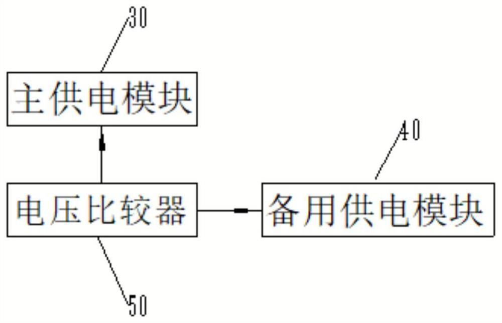
The invention provides a pole-mounted circuit breaker power taking device, a circuit breaker mounting structure and a power taking method. The pole-mounted circuit breaker power taking device comprises a circuit breaker body, a feeder terminal electrically connected to the circuit breaker body and used for controlling opening and closing of the circuit breaker body, a main power supply module that comprises a current transformer that is electrically connected with the feeder terminal and converts the high voltage into a working voltage required by the feeder terminal and transmits the working voltage to the feeder terminal, a standby power supply module, and a transformer chamber; the standby power supply module comprises an energy storage unit and a transformer chamber electrically connected with the energy storage unit, the energy storage unit is arranged on the circuit breaker body and used for storing electric energy, and the transformer chamber is electrically connected with the feeder terminal; and the transformer chamber is used for converting the high voltage obtained by the energy storage unit into a working voltage required by the work of the feeder terminal and transmitting the working voltage to the feeder terminal. The pole-mounted circuit breaker power taking device and the pole-mounted circuit breaker power taking method provided by the embodiment of the invention can improve the reliability and the safety of the pole-mounted circuit breaker.

Description

technical field [0001] Embodiments of the present invention generally relate to the circuit breaker field, and more specifically, relate to a pole-mounted circuit breaker power taking device, a circuit breaker installation structure and a power taking method. Background technique [0002] With the continuous development of smart grids, people's requirements for intelligent electrical equipment are also increasing, and the boundaries between primary and secondary equipment will become increasingly blurred. In this regard, the State Grid Corporation is vigorously promoting the integration of primary and secondary electrical equipment. Trying to break the existing pattern of electrical equipment. [0003] The traditional pole-mounted circuit breaker is composed of three parts: the circuit breaker body, the feeder terminal and the voltage sensor. The composition is cumbersome, there are many leads, and the installation is complicated. The terminal will lose the power supply, an...

Claims


Application Information

Patent Timeline
IPC IPC(8): H02J9/04H01H71/08
CPCH02J9/04H01H71/08Y02B70/30Y04S20/20
Inventor 耿凯荣庆玉王晓磊赵如杰任君李连召张峰李嘉洋
Owner 山东汇能电气有限公司
Features
  • R&D
  • Intellectual Property
  • Life Sciences
  • Materials
  • Tech Scout
  • Unparalleled Data Quality
  • Higher Quality Content
  • 60% Fewer Hallucinations
Learn More