Method for controlling locking force of locking device

A technology of locking device and control method, which is applied in the direction of excitation or armature current control, etc., can solve problems such as changes in locking effects, achieve reliable locking states, improve control accuracy, and solve the effects of excessive friction changes

Active Publication Date: 2022-02-25
JIUJIANG JINGDA MEASUREMENT TECH
View PDF10 Cites 0 Cited by
  • Summary
  • Abstract
  • Description
  • Claims
  • Application Information

AI Technical Summary

Problems solved by technology

[0005] The object of the present invention is to provide a method for controlling the locking force of a locking device, which can overcome the influence of the magnetic field change of the DC motor of the locking mechanism and the resistance change of the transmission member, and solve the problem of the existing locking device. Working under different temperature conditions, the locking effect will have obvious changes

Method used


Image

  • Method for controlling locking force of locking device

Examples


Embodiment Construction

[0025] The following will clearly and completely describe the technical solutions in the embodiments of the present invention with reference to the accompanying drawings in the embodiments of the present invention. Obviously, the described embodiments are only some, not all, embodiments of the present invention. Based on the embodiments of the present invention, all other embodiments obtained by persons of ordinary skill in the art without creative efforts fall within the protection scope of the present invention.

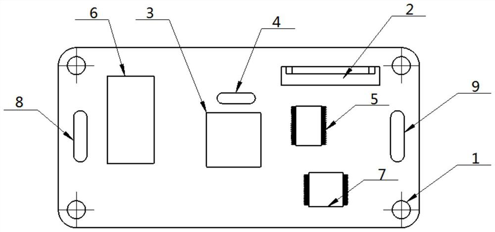
[0026] see figure 1 As shown, the present invention is a method for controlling the locking force of a locking device, including a controller 1, the controller 1 including a DC motor driver 2, a main control chip 3, a temperature sensor 4, an AD sampling chip 5, Power module 6, Flash chip 7, RS422 power supply serial port input terminal 8, locking device connector 9;

[0027] Its control method steps are as follows:

[0028] SS01: Install the controller 1 as a wh...


PUM


Abstract

The invention discloses a method for controlling the locking force of a locking device, which relates to the technical field of industrial automation. A controller is arranged, the controller comprises a direct current motor driver, a main control chip, a temperature sensor, an AD sampling chip, a power supply module, a Flash chip, an RS422 power supply serial port input end and a locking device connector, and further comprises a high and low temperature constant temperature box and a torque sensor which are used for measurement. The influence caused by the magnetic field change of the direct current motor of the locking mechanism and the resistance change of the transmission part can be overcome, the locking force of the locking mechanism can be ensured to be basically unchanged, and the locking state is more reliable. And the locking force can be configured through software, hardware does not need to be changed, and the control precision of the locking force of the locking mechanism is greatly improved.

Description

technical field [0001] The invention belongs to the technical field of industrial automation, in particular to a method for controlling the locking force of a locking device. Background technique [0002] With the development of navigation technology in our country, single-axis and multi-axis inertial navigation equipment has been widely used in military and civilian fields. The locking device can provide functions such as reference zero position and position locking for single-axis and multi-axis navigation equipment, and is an important part of inertial navigation equipment. [0003] The traditional control method of the locking force of the locking device is to set the current value of the final locked state as a fixed value; from the force formula of the current-carrying conductor in the magnetic field: F=BIL, it can be known that the magnetic field strength B of the motor and the coil length L are fixed. value, when the current is fixed, the output torque of the motor ...

Claims


Application Information

Patent Timeline
Patent Type & Authority Applications(China)
IPC IPC(8): H02P7/29
CPCH02P7/29
Inventor 徐小宗王星星任梦晴刘海涛吴昊
Owner JIUJIANG JINGDA MEASUREMENT TECH
Why Eureka
Try Eureka