Relay valve for a pneumatic valve unit

A technology of relay valve and valve unit, which is applied in the field of relay valve for pneumatic valve unit, can solve the problems of high manufacturing cost and the like

Pending Publication Date: 2022-02-25
ZF CV SYST EURO BV
View PDF9 Cites 0 Cited by
  • Summary
  • Abstract
  • Description
  • Claims
  • Application Information

AI Technical Summary

Problems solved by technology

Although this concept of a relay valve has proven useful, its assembly involves a relatively high manufacturing effort

Method used


Image

  • Relay valve for a pneumatic valve unit
  • Relay valve for a pneumatic valve unit
  • Relay valve for a pneumatic valve unit

Examples


Embodiment Construction

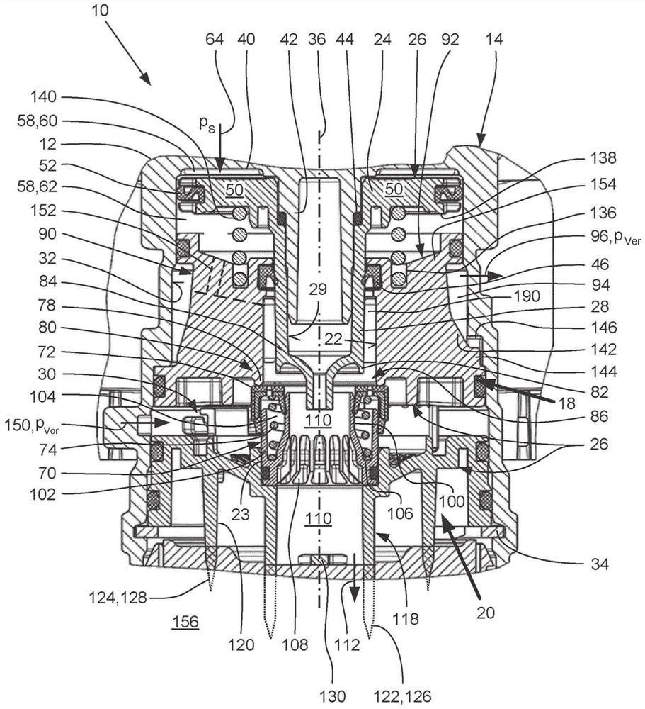
[0030] figure 1 The relay valve 10 shown in is accommodated in a housing 12 of a pneumatic valve unit 14 of a not shown brake system of a not shown commercial vehicle.

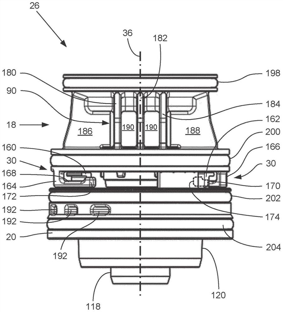
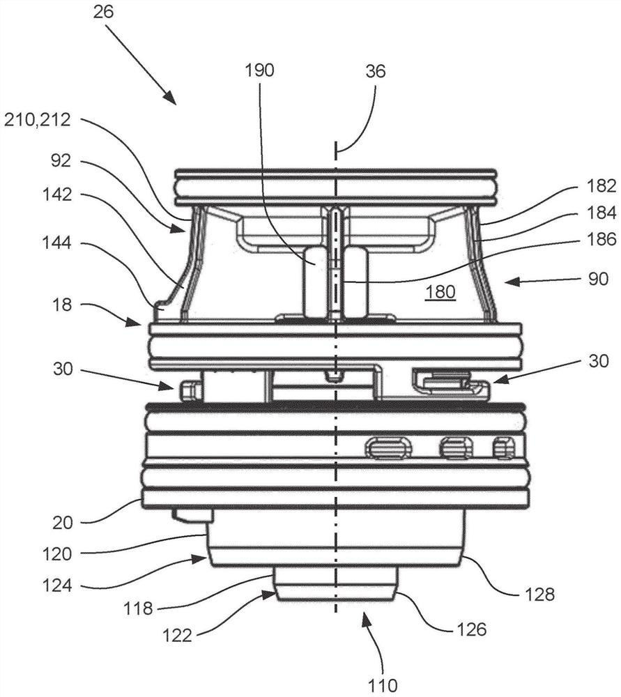
[0031] The relay valve 10 has a first assembly part 18 and a second assembly part 20 as well as a piston 24 , wherein the first assembly part 18 and the second assembly part 20 and preferably the piston 24 as a whole in the assembled state A pre-assembled unit 26 is formed. The first assembly part 18 and the second assembly part 20 are firmly connected to one another by means of a bayonet connection 30 and the hollow cylindrical guide area 28 of the piston 24 is centrally accommodated in the first assembly part in an axially displaceable manner. Within 18.

[0032] The pre-assembly unit 26 is inserted into the one-sided, pot-shaped and stepped inner wall 32 of the housing 12 of the valve unit 14 and is axially fixed and fastened therein by means of a retaining ring 34 only by way of example. . This results...


PUM


Abstract

The invention relates to a relay valve (10) for a pneumatic valve unit (14), for example for a valve unit for a braking system of a utility vehicle, which relay valve has a first assembly part (18) and a second assembly part (20). A hollow cylindrical guide portion (28) of a piston (24) of the relay valve (10) is or can be received, in an axially guided manner, in the first assembly part (18). The second assembly part (20) comprises additional valve components and the venting region of the relay valve (10). According to the invention, at least the first assembly part (18) and the second assembly part (20), when assembled, form a preassembled unit (26); the first assembly part (18) and the second assembly part (20) are joined by means of a bayonet connection (30) in order to produce the preassembled unit (26); and the preassembled unit (26) is inserted into an interior of a housing (12) of the valve unit (14), which interior is delimited by a cup-shaped inner wall (32), and the preassembled unit is fastened therein. Consequently, particularly simple and economical mounting of the preassembled unit (26) in a correspondingly designed housing (12) of the valve unit (14) is possible.

Description

technical field [0001] The invention relates to a relay valve for a pneumatic valve unit, for example for a valve unit of a brake system of a commercial vehicle, the relay valve having a first assembly part and a second assembly part, wherein , the hollow-cylindrical guide section of the piston of the relay valve is accommodated or can be accommodated in an axially guided manner in the first assembly, and wherein the second assembly has a further valve component of the relay valve and exhaust area. Background technique [0002] A relay valve for a compressed air brake system of a commercial vehicle is known from EP 2 266 854 B1. The relay valve has a housing, a relay valve piston with a relay valve piston bore arranged transversally displaceably in the housing, a relay valve with a relay valve cover bore enclosing the relay valve piston in the housing cover. The relay valve cover has at least one fastening mechanism for fastening the noise damper on the relay valve cover,...

Claims


Application Information

Patent Timeline
Patent Type & Authority Applications(China)
IPC IPC(8): B60T15/02B60T15/04B60T15/18B60T15/36B60T15/54B60T13/26
CPCB60T15/027B60T15/043B60T15/18B60T15/36B60T15/54B60T13/26B60T13/261B60T13/683
Inventor 彼得·拜尔哈特姆特·沙普勒克里斯蒂安·厄泽尔
Owner ZF CV SYST EURO BV
Why Eureka
Try Eureka