
Caliper brake

A technology of caliper brakes and braking surfaces, applied in the direction of brakes, brake types, brake components, etc., can solve problems such as disc and friction pad friction dragging, pistons cannot return smoothly, and pedal feeling is reduced, so as to improve fuel efficiency , shorten the assembly process time, improve the effect of rollback performance

Pending Publication Date: 2022-02-25
HL MANDO CORP
View PDF0 Cites 0 Cited by
  • Summary
  • Abstract
  • Description
  • Claims
  • Application Information

AI Technical Summary

Problems solved by technology

[0005] However, the problem with this conventional caliper brake is that although the elastic deformation of the sealing member during high-pressure braking is completed, the sliding of the piston that continues to advance occurs, so that the piston cannot return smoothly when the brake is released, and the disc and friction pads are damaged. frictional drag
In addition, in order to overcome this problem, when the elastically deformable movable range of the seal member is increased by enlarging the inclined surface of the seal groove in the piston advancing direction, there is an increase in the required amount of brake fluid resulting in an ineffective stroke when the brake pedal is operated. Limitations of increased and decreased pedal feel

Method used

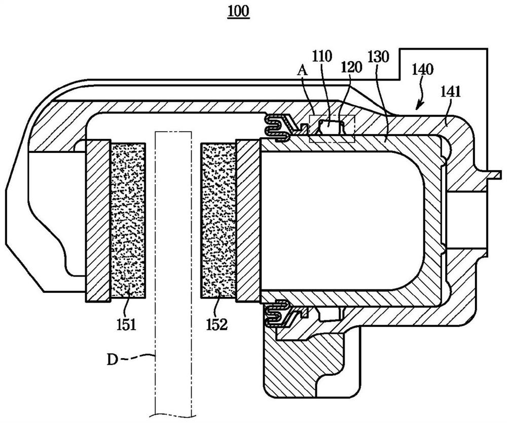
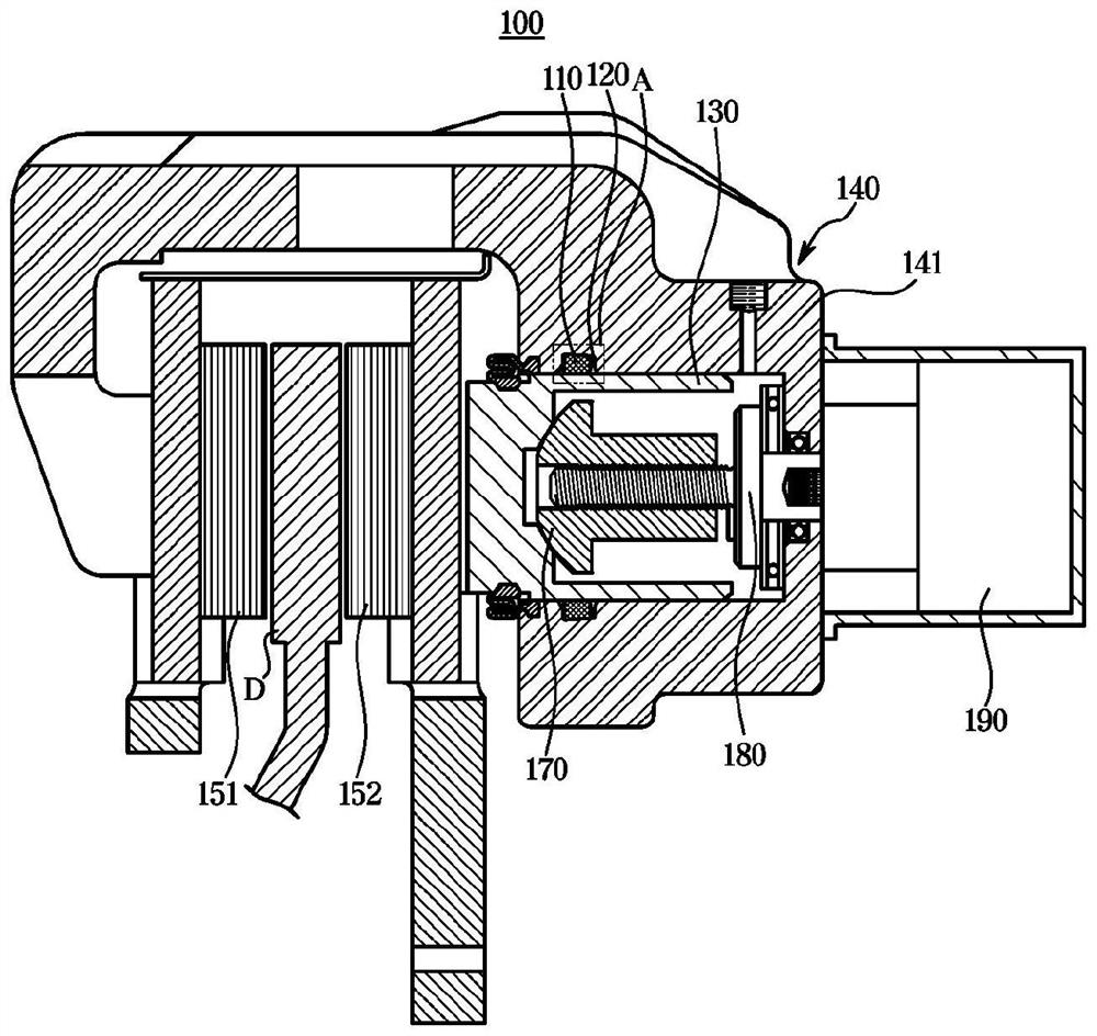
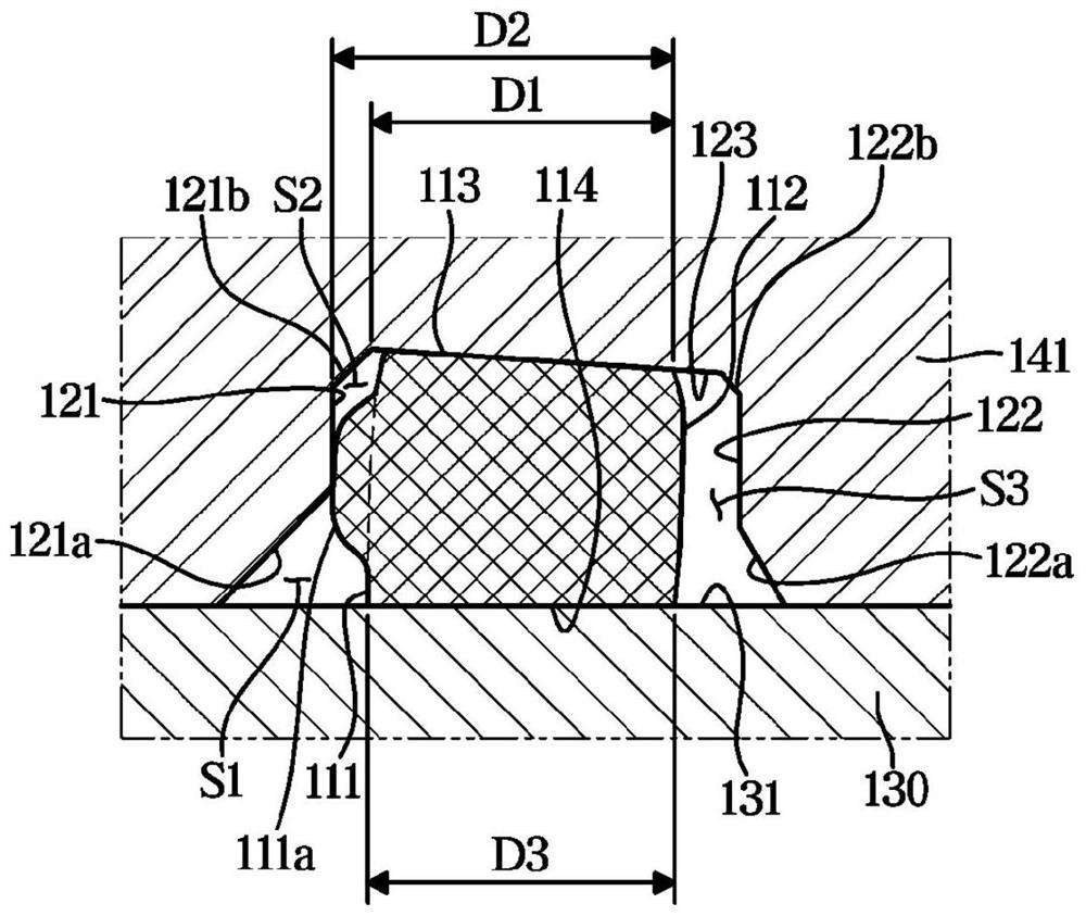

Image

  • Caliper brake
  • Caliper brake
  • Caliper brake

Examples


Embodiment Construction

[0059] best practice

[0060] Embodiments of the present invention will be described in detail below with reference to the accompanying drawings. The following embodiments are proposed in order to fully convey the idea of ​​the present invention to those of ordinary skill in the art to which the present invention pertains. The present invention is not limited to the embodiments presented here, and may be embodied in other forms. In order to clearly describe the present invention, illustration of parts irrelevant to the description is omitted, and the size of components may be slightly exaggerated to facilitate understanding.

[0061] Generally, the sealing part 110 of the caliper brake is provided in a ring shape in which the outer peripheral surface 113 is in close contact with the inner surface of the cylinder 141 and the inner peripheral surface 114 is in tight contact with the outer surface of the piston 130 . At this time, the cross section of the sealing member 110 is ...


PUM


Abstract

Disclosed is a caliper brake of the present invention. According to an aspect of the present invention, provided is a caliper brake comprising: a carrier having a pair of pad plates installed so as to advance to and retreat from a disk; a caliper housing which is slidably installed on the carrier and has a cylinder; a piston which is installed in the cylinder and can advance to and retreat from the pad plates by means of a braking hydraulic pressure; a seal groove annularly recessed in the inner surface of the cylinder; and a seal member which is accommodated in the seal groove and has a front surface positioned in the advancing direction of the piston, a rear surface positioned in the retreating direction of the piston, an inner peripheral surface coming into close contact with the outer peripheral surface of the piston, and an outer peripheral surface coming into close contact with a mounting surface of the seal groove. The front surface has a protrusion of which at least one part protrudes.

Description

technical field [0001] The present invention relates to a caliper brake, and more particularly, to a caliper brake including a sealing member that retracts a piston when the brake is released. Background technique [0002] Typically, a caliper brake includes: a disc that rotates with the wheel; a support on which a pair of backing plates are mounted and that can be advanced or retracted to pressurize the disc; and a caliper housing The body is slidably mounted on the support, and is provided with a cylinder in which a piston is mounted and can advance or retreat by brake hydraulic pressure. [0003] This type of caliper brake acts as a brake through a piston based on the pressurization of the brake hydraulic pressure, and also uses an actuator that is operated electrically to receive the rotational force of the motor, and through the spindle that converts the rotational motion into linear motion The unit pressurizes the piston, which also acts as a parking brake. At this t...

Claims


Application Information

Patent Timeline
Patent Type & Authority Applications(China)
IPC IPC(8): F16D65/18F16D121/04F16D125/08
CPCF16D65/183F16D2121/04F16D2125/08F16D55/226F16D2121/24F16D2125/40B60T13/588F16D2055/0016
Inventor 姜东求
Owner HL MANDO CORP
Learn More