
Stirring device

A stirring device and stirring shaft technology, applied in the field of concrete mixing, can solve the problems of low mixing efficiency and high processing difficulty of mixing blades

Inactive Publication Date: 2022-03-01
GUANGDONG BOZHILIN ROBOT CO LTD
View PDF5 Cites 0 Cited by
  • Summary
  • Abstract
  • Description
  • Claims
  • Application Information

AI Technical Summary

Problems solved by technology

[0003] The purpose of the embodiments of the present application is to provide a stirring device, which aims to improve the problems of high processing difficulty and low stirring efficiency of the stirring blades in the related art

Method used


Image

  • Stirring device
  • Stirring device
  • Stirring device

Examples


Embodiment

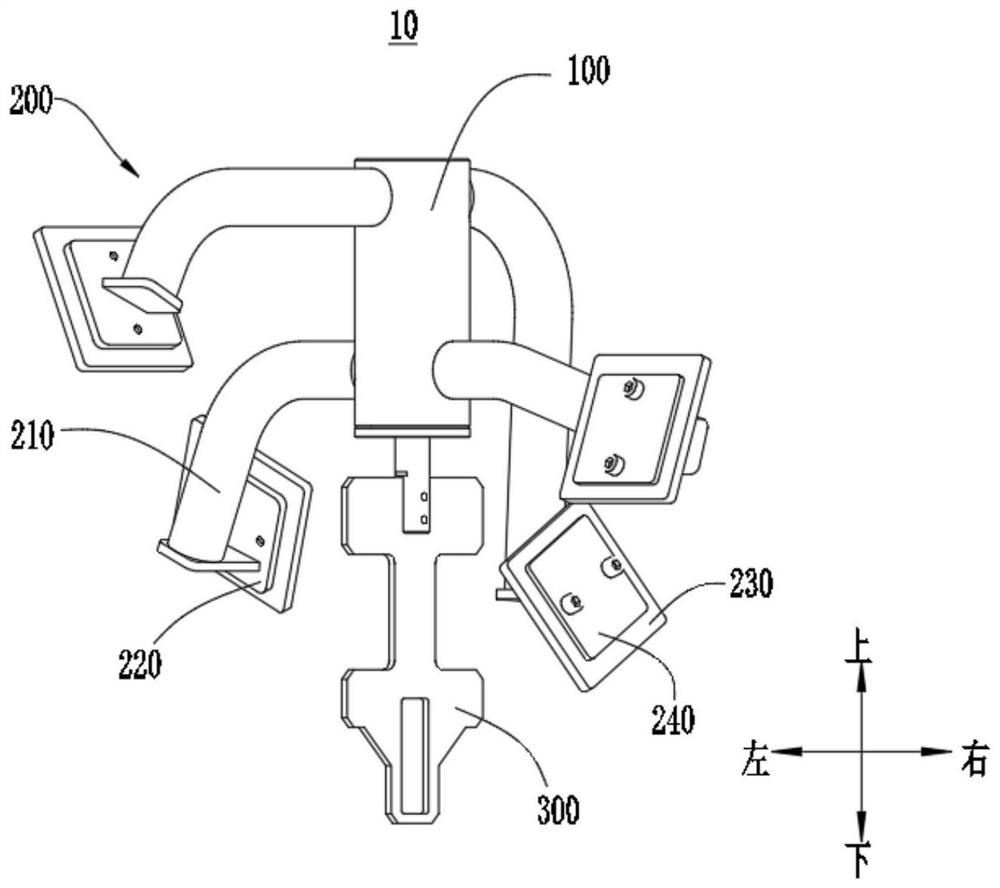
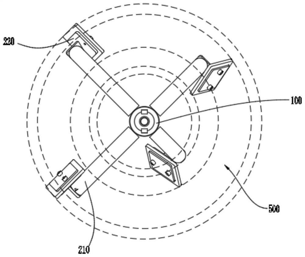
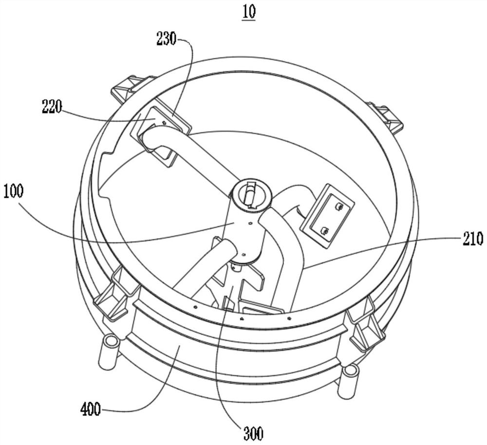
[0026] Please refer to figure 1 , this embodiment provides a stirring device 10 , the stirring device 10 includes a stirring shaft 100 and at least two stirring components 200 . Each stirring assembly 200 includes a first stirring blade 220 and a connecting rod 210 , and the connecting rod 210 connects the stirring shaft 100 and the first stirring blade 220 . At least two first stirring blades 220 are distributed up and down along the axial direction of the stirring shaft 100 . The face of the first stirring blade 220 of the upper floor is along the direction of rotation ( figure 1 From top to bottom, it is counterclockwise) to tilt downward, and the surface of the first stirring blade 220 on the lower floor is along the direction of rotation ( figure 1 Viewed from top to bottom in the counterclockwise direction) upward slope. The stirring device 10 includes a stirring shaft 100 and a stirring assembly 200, and has a simple structure and is easy to manufacture. The first s...


PUM


Abstract

The invention provides a stirring device, and relates to the technical field of concrete stirring. The stirring device comprises a stirring shaft and at least two stirring assemblies. Each stirring assembly comprises a first stirring blade and a connecting rod, and the connecting rod is connected with the stirring shaft and the first stirring blade. The at least two first stirring blades are distributed up and down along the axial direction of the stirring shaft. The slurry facing faces of the first stirring blades on the upper layer incline downwards in the rotating direction, and the slurry facing faces of the first stirring blades on the lower layer incline upwards in the rotating direction. The stirring device comprises the stirring shaft and the stirring assembly, and is simple in structure and easy to manufacture. The first stirring blades on the lower layer turn the materials upwards, and the first stirring blades on the upper layer press the materials downwards, so that the materials are turned over in the stirring barrel through cooperation, and the stirring efficiency is high.

Description

technical field [0001] The present application relates to the technical field of concrete mixing, in particular, to a mixing device. Background technique [0002] At present, there are many types of blades used for mortar concrete mixing on the market, and the shapes are different. According to the appearance, the existing types are fan-shaped, propeller-shaped, soft cross-shaped, butterfly-shaped, etc. When the above-mentioned blades are used for stirring, the slurry rotates in the same direction during the stirring process, which tends to generate eddy currents and the stirring efficiency is low. This application proposes a novel stirring device with high stirring efficiency. Contents of the invention [0003] The purpose of the embodiments of the present application is to provide a stirring device, which aims to improve the problems of high processing difficulty and low stirring efficiency of the stirring blades in the related art. [0004] An embodiment of the presen...

Claims


Application Information

Patent Timeline
Patent Type & Authority Applications(China)
IPC IPC(8): B28C5/16
CPCB28C5/16B28C5/0806B28C5/0862
Inventor 邬宇强韩冰邹亮苏俊超刘阳
Owner GUANGDONG BOZHILIN ROBOT CO LTD
Learn More