Train control method, storage medium, vehicle controller and train
A train control and train technology, which is applied to the control system of the transportation center, railway car body parts, railway signal and safety, etc., can solve the problem of high cost, reduce the quantity, reduce the complexity of control logic, and reduce the cost of laying and maintenance Effect
Pending Publication Date: 2022-03-01
BYD CO LTD
10 Cites 0 Cited by
AI-Extracted Technical Summary
Problems solved by technology
[0005] The purpose of this disclosure is to provide a train control method, storage m...
Method used
Increase camera on train, gather the image information on train traveling direction, even if trackside equipment breaks down, train also can determine the control strategy of train according to the image information of gathering, has improved train obstacle avoidance ability, and then improved train Control stability and security.
Optionally, traffic direction display and transit time display can be arranged on the display area of same signal lamp, like this,...
Abstract
The invention relates to a train control method, a storage medium, a vehicle controller and a train, and aims to solve the problem of high cost of train control. Comprising the steps that passing direction information, passing time information and the current running speed of a train are obtained, first distance information between the train and a signal lamp is obtained, and the passing direction information and the passing time information are displayed through the signal lamp arranged on a target turnout; according to the current driving speed, the first distance information, the passing direction information and the passing time information, whether the train can pass a target turnout indicated by the passing direction information is determined; and under the condition that the train can pass through the target turnout, the train is controlled to run to pass through the target turnout. Therefore, the number of trackside equipment such as axle counters and signal lamps can be reduced, and the train control cost is reduced. And the camera is additionally arranged on the train, so that the autonomous motility of the train can be improved, the obstacle avoidance capability of the train is improved, and the rationality and safety of train control are further improved.
Application Domain
Railway traffic control systems
Technology Topic
Obstacle avoidanceAxle counter +5
Image
Examples
- Experimental program(1)
Example Embodiment
[0034] DETAILED DESCRIPTION OF THE PREFERRED EMBODIMENTS It should be understood that the specific embodiments described herein are intended to illustrate and explain the disclosure and is not intended to limit the disclosure.
[0035] It should be noted that the term "first", "second", "second", etc. in the appended claims,,,,,,,,,,,,,,,,,,,,,,,,,, . Similarly, the terms "S11", "S12", and the like are used to distinguish the steps, without having to understand the method steps in accordance with a particular order or intern order.
[0036] Introduction to the train control method, storage medium, vehicle controller, and train provided by the present disclosure, first introduces the application scenarios of the various embodiments of the present disclosure, and various embodiments of the present disclosure can be applied to, for example, urban orbit trains, for example, The train control method can be applied to the vehicle controller of the train, and can also be applied to other controllers, such as a vehicle fault detection controller.
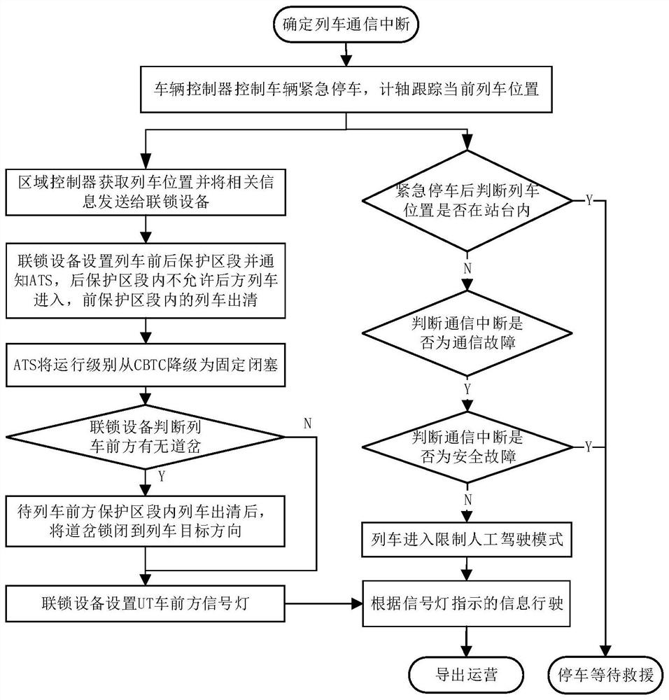
[0037] refer to figure 1 As shown, in the related art, when it is determined that the train is in communication interruption, the vehicle controller controls the train emergency parking, and the shaft tracks the current train position. After the emergency stop, it is judged whether or not the train position is in the station, and the train position is reported to the region controller. The regional controller sends information including the travel section of the train to the interlocking device, and the interlocking device sets the non-communication train before and after the protected section and notifies the ATOMATIC Train Supervision train automatic monitor subsystem), which is not allowed to allow rear train Enter the rear protected section, and have entered the train within the reserve protection area to achieve emergency brake parking; set the train in the front protected area. Further, the ATS reduces the operational level to a fixed occlusion, and the interlocking equipment determines whether there is a way in the front protected area of the non-communication train. If there is a way, after the train is in the front of the reserve segment, the Taxi is locked. Go to the traitor direction, interlocking equipment sets the signal light front signal light; if there is no road, the interlock device sets the front signal light, the vehicle controller is driven according to the signal light control, and the operation is exported.
[0038] In this way, the rail-based equipment is high, and the automatic monitoring subsystem needs to integrate control logic of each interlocking device, the control logic of the train automatically monitor subsystem is complex. In addition, there is a failure of any tracking device in the train operation section, and the train operation will be affected. The train runs without independent decision-making power, causing the train to operate the stability of the train.
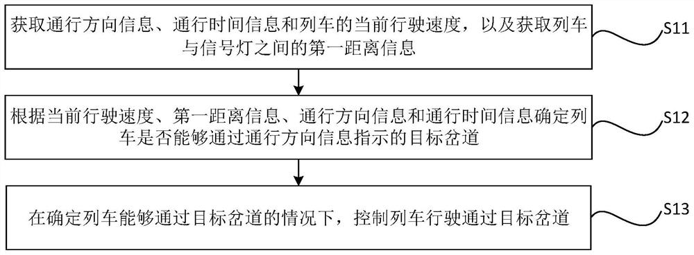
[0039] In order to achieve the above object, the present disclosure provides a train control method, is applied to the train, and the vehicle controller acts as a train control method as an example, reference figure 2 A flow chart of a train control method, the train control method includes:
[0040] S11, acquires the current direction information, the current time information, and the current travel speed of the train, and acquires the first distance information between the train and the signal light.
[0041] The passing direction information and the passage time information are displayed by a signal light placed on the target.
[0042] S12, based on the current travel speed, the first distance information, the passing direction information, and the passage time information, determines whether the train can be indicated by the travel direction information indicated by the passage.
[0043] S13, in determining that the train can pass through the target irrational channel, control the train through the target.
[0044]Specifically, the vehicle controller can pass the passive direction information and the passage time information displayed by the camera, the camera is connected to the train controller, exemplary, by the bus and the vehicle controller, such as the CAN bus, can also be connected. Wireless mode communication with vehicle controller, such as 5G communication mode.
[0045] The camera can transmit the general direction information displayed in the collected train in the general direction display to the vehicle controller, and can transmit the passage time information displayed in the acquired train running direction to the vehicle controller.
[0046] Alternatively, the passing direction display and the traffic time display can be set to the display area of the same signal light, which can reduce the time cost and material cost of the signal light harness, save the arrangement of the wire beam; the general direction display and the traffic time display can also be set. Different signal lights, the signal light can maintain a certain distance so that the traffic direction information and the traffic time information of the display can be avoided, which can improve the accuracy of the camera acquisition information.
[0047] Alternatively, the passing direction display can display different password symbols, characterize different traffic direction information. For example, the passing direction display displays different arrow symbols to characterize different vertical directions, examples, and the passing direction display shows the arrows to the left side can pass the left side of the target, and the passing direction display shows the right side of the arrow to characterize the target. The side trunks can be accepted, and the passing direction display displays the arrows to characterize the target irregular track direct line, and the cross-direction display shows the cross-track switching state.
[0048] Alternatively, the vehicle controller can obtain the current travel speed from the wheel speed sensor, or the current travel speed can also be analyzed from the drive device. In this way, the first distance information of the train and the signal light can be calculated according to the time of the radar transmitted signal, and the current travel speed.
[0049] Further, the vehicle controller receives the passive direction information and the traffic time information collected by the camera, and can determine whether the target direction of the train is determined in the target direction of the travel direction information, if the target is in the target The passing direction is not a target traffic direction, and the vehicle controller controls the train according to the pass time information.
[0050] In a possible implementation, the vehicle controller determines that the target irrational channel is in the macro switching process according to the pass direction information, and the vehicle controller is determined in the train according to the traffic time information during the target direction. When the current driving speed reaches the target, the target irration has been switched to the target direction, and the vehicle controller control train maintains the current travel speed through the target.
[0051] Example, the vehicle controller determines according to the traffic time information to reach the target in accordance with the current travel speed, the target ratio is still in the target direction switching process, and the vehicle controller controls the train brakes to speed up, to control the train to switch in the target Before the target direction, the target is not reached, so that the vehicle controller controls the train through the target.
[0052] The above technical solution is obtained by acquiring the current traveling speed of the traffic direction information, the traffic time information, and the first distance information between the train and the signal light, and in accordance with the current driving speed, the first distance information, the traffic direction information and the passage. The time information determines whether the train can be indicated by the traffic direction information, and the control train can be driven through the target in the case where the train can pass through the target frame. In this way, it can reduce the number of rails and other rails, reduce the laying and maintenance cost of the railway device, and the train can reduce the train automatic monitoring subsystem according to the operating state of the acquired traffic direction information and the pass time information Control logic complexity. For example, there is no need to set the signal light in the non-ferry area, saving the cost of rail construction, and does not require the shaft to determine the travel section of the train, and there is no need to distribute the train travel of the train without the regional controller, and the complexity of system control is reduced.
[0053] Alternatively, the camera can include a camera, for example, the camera can be an infrared camera, a high-definition imaging head, or a panoramic camera, and the camera may also include a plurality of cameras, and the plurality of the camera is set at different orientations of the train head. For example, The camera can be three cameras disposed at the front left front of the train head, the forward and right front, and the plurality of cameras are used to collect different orientations in different directions in different directions and the passing direction information and the passage time. information.
[0054] Specifically, reference image 3 The camera is schematically illustrated, three cameras in the train, three cameras toward the left front of the train head, forward and right forward. Among them, the camera of the left front is used to collect the passive direction information and pass time information displayed in the left front signal light in the train direction. When the target mutter is in the left-turn section, the left front camera can be collected to the path of the left front signal light. And pass time information. The front camera is used to collect the traffic direction information and pass time information displayed in the forward signal light in the train direction. When the target raceway is in the execution section, the front of the front camera can collect the traffic direction information and pass time of the forward signal light. information. The right front camera is used to collect the passive direction information and the pass time information displayed in the train direction of the train. When the target mutter is in the right turn section, the right front camera can be collected to the passing direction information and passage of the right front signal light. Time information. In this way, it is possible to ensure that the camera can accurately collect the traffic direction information and the traffic time information displayed by the signal light, which can improve the accuracy of the acquisition pass direction information and the traffic time information.
[0055] In the train, the camera is added, the image information in the train travel direction is collected. Even if the railway device is faulty, the train can also determine the control strategy of the train according to the collected image information, improve the train avoidance ability, and increase the stability of the train control. Sex and safety.
[0056] Alternatively, the passing direction information includes a signal color information, the passage time information including a second countdown information;
[0057] Specifically, the signal lights different color characterization of the target irrational tracks, the second countdown information is used to characterize the passing countdown time corresponding to the passing direction. For example, the signal light display green characterization Current direct allowation, the number of second countdown information displays the number of seconds number of seconds that the target irrigation can pass the number; the signal light display yellow characterization target irrigation channel is in the mutual channel switch, the number of second countdown information shows the number of seconds countdown The signal light displays the red characterization target irrigation channel can pass, and the number of second countdown information shows the number of seconds of the target in the left front of the target. The signal light shows the blue characterization target irrigation channel is in the right, the number of countdown information shows the right side of the target. The number of seconds that can be passed will count down.
[0058] refer to Figure 4 A flow chart of a train control method, the train control method includes:
[0059] S21, through the camera acquisition the signal color information and the second countdown countdown information, through the radar acquire the first distance information between the train and the signal light and the current travel speed from the wheel speed sensor.
[0060] S22, according to the current driving speed, the first distance information, the signal color information, and the second countdown time information determines whether the train can be indicated by the travel direction information.
[0061] S23, in determining that the train can pass through the target frame, control the train through the target.
[0062] Specifically, the vehicle controller obtains the signal color information by the camera, and determines the direction of the travel direction of the target in accordance with the signal color information, and then obtains the number countdown information by the camera, and determines whether the train can pass according to the number of second countdown information. Target forces indicated by the traffic direction information.
[0063] For example, the signal color information characterizes the direct direction of the target irrigation channel, and the target direction of the vehicle controller is also straightforward, the vehicle controller determines the direction of the traveling direction of the target, and the second countdown information characterization can pass In the case of 20 seconds left, the vehicle controller determines the trains through the target irrational track by the target irrational channel indicated by the traffic direction information according to the second number of seconds of 20 seconds.
[0064] Optionally, reference Figure 5 A flow diagram of a train control method, in step S11, the current travel speed of the passing direction information, the pass time information, and the train, and the first distance information between the train and the signal light, including:
[0065] S111, obtain communication status information of the train and train automatically monitor subsystems.
[0066] S112, determine whether the train is automatically monitored by the train to interrupt if the train is automatically monitored by the train.
[0067] S113, in the case where the communication status information is characterized by the train to automatically monitor the subsystem communication interruption, the current travel speed of the traffic direction information, the passive time information, and the train is acquired, and acquire the train and the signal light. The first distance information.
[0068] Specifically, the vehicle controller acquires the communication status information of the train and the train automatically monitors the subsystem. When the train is automatically monitored by the trail, the train automatically monitors the subsystem to obtain the traffic direction information of the target Tank's signal display. And the traffic direction information, thereby the vehicle controller can automatically monitor the penetration information and the traffic direction information of the subsystem to acquire the subsystem, thereby controlling the train through the target in the case where the train can pass.
[0069] In the case where the train is automatically monitors the subsystem communication interruption, the vehicle controller acquires the passing direction information and the passage time information through the camera, and obtains the first distance information between the train and the signal light through the radar and obtains the current driving speed from the wheel speed sensor. In order to determine that the train can pass, the control train passes the target.
[0070] Thus, in the case where the train is in a non-communication state, the dependence of the rails such as the arranging axis can be reduced, and the signal light is only determined according to the traffic direction preset time information, and the signal light does not need to change according to the communication status of the train. The mode reduces the complexity of CBTC system control. Further, when the train is in a non-communication state, there is no need to determine the front and rear protected section, but there is no need to clear the train operation in the train, and improve the efficiency of the train operation.
[0071] Alternatively, the method further includes acquiring the travel direction of the train at the target irrigation channel.
[0072] refer to Image 6 A flow chart of a train control method, the train control method includes:
[0073] S61, acquires the passing direction information, the current travel speed of the train, and the first distance information between the train and the signal light.
[0074] S62, get the target pass direction of the train.
[0075] S63 determines whether the first pass direction indicated by the target pass direction and the passage direction information is consistent.
[0076]S64, in the case where the target pass direction and the first passage direction are consistent, according to the passage time information and the first distance information, it is determined whether or not the train can travel by the current travel speed. Target forces indicated by the traffic direction information.
[0077] S65, when determining that the train can travel by the current travel speed, by the target frame indicated by the passing direction information, controlling the train by the current travel speed through the target.
[0078] Specifically, the image information of the signal light can be acquired by the camera, and the passage direction information and the passage time information can be acquired, and the time difference between the radar transmitting signal and the reception reflection signal, and the current driving speed, the train and the signal light can be determined. The first distance information between.
[0079] Specifically, the vehicle controller can acquire the target access direction from the ATS, or can acquire the target passage direction from the train operation curve.
[0080] refer to image 3 A radar and camera installation diagram showing the laser radar and millimeter wave radar installed in the train head, reference Figure 7 A block diagram of a radar and a camera embodiment, the radar is communicatively connected to the obstacle detecting device, and the obstacle detecting means communicates with the vehicle controller. The camera communicates with the image recognition device, the image recognition device communicates with the vehicle controller.
[0081] Specifically, millimeter wave radar is mounted at a lower position near the ground near the ground, and is used to detect a signal light from the forward direction, and the laser radar is mounted on the train head away from the higher position, for detecting the direction of the forward direction. Far and signal lights around the track. The obstacle detecting device determines the first distance of the target signal light and the train according to the reflected signal of the radar transmitting signal and the target signal light, and the vehicle controller determines the train according to the travel speed of the train, the pass direction information, the pass time information, and the first distance information. Whether it is possible to indicate the target inversion of the traffic direction information.
[0082] Example, the laser radar detects that there is a target frame and a corresponding signal light in the travel direction, and the obstacle detecting device determines that the distance from the transmitted signal and the transmit signal according to the laser radar is 200 meters, and the distance is transmitted to the vehicle control. .
[0083] Further, the obstacle detecting device determines that the exact distance of the train and the signal light is 196 meters according to the transmitted signal and the transmit signal of the millimeter wavele, and the exact distance is transmitted to the vehicle controller. The vehicle controller acquires the image recognition device through the passage of the signal of the signal and the pass time information of the signal collected by the camera.
[0084] Optionally, Figure 8 Be an implementation Image 6 The exemplary flow chart of step S64 in step S64. In step S64, in the case where the target general direction and the first passage direction are consistent, the train is determined in accordance with the passage time information and the first distance information, whether the train can be driven by the current travel speed. The target ratio indicated by the passing direction information includes:
[0085] S641, which is consistent in the target pass direction and the first passage direction, according to the passage time information, and the first distance information, it is determined that the train can travel by the current travel speed cannot pass the passage direction information. In the case of a target irrational track, the maximum speed limit of the target irrigation channel is obtained.
[0086] S642, according to the current travel speed, determines the first time information and acceleration information of the maximum speed to the maximum speed limit.
[0087] S643, according to the first time information, the acceleration information, the passing time information, and the first distance information, it is determined whether the train can travel by the maximum speed can be indicated by the passing direction information. Rafter.
[0088] In step S65, in the case where the train can be used, the train can be controlled through the target, including:
[0089] In the case where the train can run through the target frame indicated by the truck by the maximum speed information, the train acceleration is controlled according to the acceleration information.
[0090] Example, the current travel speed of the train is 180 kilometers. The first distance information characterizes the distance of 200 meters, and the pass time information is characterized by 5 seconds after 5 seconds. Determine whether the train accelerates to the maximum speed of 200 kilometers can pass the target ink, where the train length is required, and the train tail is passed through the target irrigation channel, the target irrigation latter starts to switch the action.
[0091] refer to Figure 9 A flow diagram of a train control method, after step S63, the method further includes:
[0092] S91, in the case where the target pass direction and the first passage direction are inconsistent, determine the passing direction of the target frame to the second time information consistent with the target pass direction according to the passage time information.
[0093] S92, according to the second time information and the first distance information, it is determined that the train is running to the target frame by the current running speed, whether the direction of the target holder has been switched to the target The pass direction is consistent;
[0094] S93, in the case where it is determined that the penetration direction of the target frame has been switched to the target pass direction, control the train to travel at the current travel speed.
[0095] Example, according to the traffic time information displayed in the signal display to switch to the second time information consistent with the target inline direction to 10 seconds, the first distance of the train distance is 200 meters, the train is currently driving It takes 12 seconds to travel to 600 meters per hour, and the trains have been switched to the target path when the train is traveling to the target irrational road, and the control train travels to the target in the target.
[0096] It is worth explanating that the time required for the target irration switch is required here.
[0097] Alternatively, the method further includes determining that the train is running to the target in accordance with the second time information and the first distance information. When the direction is not switched to the case of the target pass direction, the speed reduction information is determined according to the first distance information and the second time information;
[0098] The train is slowed down based on the deceleration information.
[0099] Example, when the train is running at a running speed of 120 km per hour, the vehicle controller can not be passed according to the maximum acceleration, and the vehicle controller may not pass according to the target race, according to the maximum acceleration path, and the vehicle controller may not pass the target. The first distance calculates the parking acceleration, it can determine the appropriate braking acceleration to avoid rapid brakes to ensure the comfort of the passengers.
[0100] In one case, according to the first distance information and the pass time information, the train decelerates to a driving speed. When the train reaches the target, the target irration has been switched to the target pass direction, then determines the braking deceneration of the train, and The control train runs at the brake deceleration to decelerate to the corresponding travel speed, and control the train by a specified travel speed through the target.
[0101] In another case, according to the first distance information and the traffic time information, the train is stopped by the current driving speed, and still needs parking waiting for the target frame to switch to the target traffic direction, the control train is stopped.
[0102] Alternatively, in the case where the train cannot be controlled by the preset brake parking acceleration in the case of the target frame indicated by the passing direction information according to the passive direction information and the passage time information. .
[0103] Example, the vehicle controller determines that the target irrational track is in the frame switching process according to the traffic direction information, and the vehicle controller is determined in accordance with the traffic time information in accordance with the transmission time information, and the vehicle controller is determined in accordance with the traffic time information. When the driving speed reaches the target, the target irrigation channel is not in the target direction, the vehicle controller controls the train brake deceleration or brake parking.
[0104] Yet another example, the vehicle controller determines that the target irrational path is in the muting channel switching process according to the traffic direction information, and the vehicle controller is determined in the train according to the traffic time information in the non-target direction. When the current driving speed reaches the target, the target irrational track is still in the ramp switching process, the vehicle controller controls the train brake deceleration or brake parking.
[0105] Alternatively, the method also includes:
[0106] The track image information in the travel direction of the train is obtained by the camera;
[0107] In the case where the track image information is characterized by an obstacle on the track, the second distance information between the train and the obstacle is acquired by the radar;
[0108] According to the current travel speed and the second distance information, the brake acceleration of the train is determined;
[0109] The train is controlled according to the brake acceleration.
[0110] Specifically, the camera can collect image information of the track, and it is possible to determine whether there is a target obstacle on the track, for example, whether there is a parked faulty vehicle on the track, whether there is a stone such as a stone on the track. The obstacle detecting device can detect the second distance between the target obstacle and the train on the track by radar, and the vehicle controller can determine the brake parking acceleration according to the current travel speed and the second distance of the train, to ensure the train in the target barrier Brake the parking before collision, and then wait for the rescue.
[0111] Alternatively, the target obstacle includes a front train that travels on the track, which can solve the safety accident that the train in the relevant technologies can be in communication interruption. It will be appreciated that the vehicle controller can also determine the travel speed of the front train according to the second distance information of the radar persistence and the train of the front train, and then determine the second start parking acceleration, and according to the second Brake park acceleration travel.
[0112] The train control method of the present disclosure will be described in detail by the specific embodiment. Figure 10 A flow chart of a train control method, the train control method includes:
[0113] S801, the vehicle controller acquires the communication status information of the train and the train automatically monitors the subsystem.
[0114] Alternatively, according to the communication status information, the communication state of the train and the train is automatically monitored, and in the case where the train and the train automatic monitoring subsystem is in normal state, the vehicle controller is automatically monitored by the train automatically monitor the control instruction of the subsystem. Control the train. Otherwise, step S802 is performed, and if the train is used to automatically monitor the subsystem in communication, it is judged whether or not the train security failure causes the communication interruption.
[0115] In determining that the train security failure causes the communication interruption, step S803 is executed, and the control train is braked according to the preset braking information and waits for rescue.
[0116]In the case where it is determined that the traffic is not caused by the train, it is performed to perform the track image information in the train travel direction.
[0117] S805, the vehicle controller determines whether there is a fork in the travel direction of the train according to the track image information.
[0118] When it is determined that there is no parking direction in the travel direction, step S806 is performed, and the vehicle controller control train continues to travel.
[0119] In the case where the train is determined in the travel direction, step S807 is performed, the current travel speed and the target pass direction of the train are acquired, and the signal light color information and the number countdown countdown information are acquired by the camera, and the first distance information of the train and the ink track is obtained. .
[0120] S808, it is determined whether the first pass direction indicated by the target pass direction and the passage direction information is consistent.
[0121] When it is determined that the target pass direction is consistent with the first passage direction indicated by the passage direction information, step S809 is performed, and the vehicle controller determines the train in accordance with the first distance information, the signal light color information, and the number of second countdown information. Whether the driving speed can travel in front.
[0122] In the case where the train can travel in the current travel speed, step S806 is performed.
[0123] In the case where the train is not able to travel in the current travel speed, step S810 is performed to obtain the highest speed limit of the front stroke.
[0124] S811, according to the current driving speed, determine the first time information and acceleration information of the train to the maximum speed limit.
[0125] S812, according to the first time information, acceleration information, passing time information, and first distance information, determine whether the train can travel by the highest speed limit can pass through the passage direction information indication.
[0126] In the case where the train can run by the maximum speed transmission can pass through the target frame indicated by the passage information, step S813 is performed, and the train acceleration is controlled through the target irrational channel according to the acceleration information.
[0127] In determining that the train is not capable of running through the target frame indicated by the maximum transmission information, step S814 is performed, and the current travel speed determines the acceleration of the train brake stop according to the first distance information. Information, and control the train to brake parking with the acceleration information.
[0128] In the case where it is determined that the target pass direction is inconsistent, step S815 is performed, and step S815 is performed according to the passage time information to switch to the direction of the target. Consistent second time information.
[0129] S816, according to the second time information and the first distance information, determine whether the train is running to the target frame in the current running speed, whether the direction of the target mutant channel has been switched to the target The pass direction is consistent.
[0130] In the case where it is determined that the passing direction of the target irration has been switched to the same as the target pass direction, step S806 is performed.
[0131] In the case where it is determined that the passing direction of the target irration is not switched to the same as the target pass direction, step S814 is performed.
[0132] The present disclosure also provides a signal light control method, is applied to a signal light, optionally, a control device applied to the signal light, the signal light including a traffic direction display and a pass time display, reference Figure 11 A flow chart of a signal light control method, the signal light control method includes:
[0133] S51, in response to the operation of the end of each target irration passage, acquires the trip switching information.
[0134] S52, according to the channel switching information, display the passing direction information and the passage time information.
[0135] The passing direction information is displayed by the passing direction display, the passing time information is displayed by the passage time display.
[0136] Specifically, the control device of the signal light communicates with the target frame controller, and the target rotation channel controller is used to control the target rotational switching direction. The control device of the signal light receives the Tooth switching information transmitted by the target frame controller.
[0137] Specifically, reference Figure 12 A flow chart of a signal light control method, the signal light control method includes:
[0138] S1101, the mutant channel controller controls the target frame to switch to the direct direction.
[0139] S1102, the passing direction display shows the bright green light, the passage time display displays 30 second countdown.
[0140] S1103, it is determined whether the passage time display shows whether or not the 30 second countdown ends.
[0141] If it is determined that the traffic time display shows the 30 second countdown, the S1104 is executed, and the rotary channel controller controls the target frame starts to switch to the lateral direction, and the S1105 is executed, the traffic direction display green light is lit, execute S1106, and the traffic time display is displayed for 60 seconds. Countdown information.
[0142] In turn, S1107 is executed, and it is determined whether the traffic time display is overdunting if the 60 second countdown is ended, and the rotation channel controller controls whether the target frame is switched to whether it is successful.
[0143] If it is determined that the traffic time display shows the 60-second countdown, the rotary channel controller controls the target frame switch to the lateral direction, then the S1108 is executed, and the traffic direction display red light is off, and the yellow light point bright pass time display shows yellow light countdown information.
[0144] Alternatively, the display passing direction information includes displaying different signal light color characterization of the passage direction information; and / or,
[0145] The display passing time information includes displaying a number of countdown time information.
[0146] Based on the same inventive concepts as the train control method, the present disclosure also provides a vehicle controller, including:
[0147] Memory, there is a computer program on it;
[0148] The processor is used to perform the computer program in the memory to achieve the steps of the train control method described above.
[0149] The present disclosure also provides a computer readable storage medium, which stores a computer program, characterized in that the program performs the step of implementing the signal light control method according to any of the described above.
[0150] Based on the same inventive concepts as the signal light control method, the present disclosure also provides a signal light, including:
[0151] Memory, there is a computer program on it;
[0152] The processor is used to perform the computer program in the memory to achieve the step of controlling the signal control method of any of the above.
[0153] Figure 13 It is a block diagram of an electronic device 800 according to an exemplary embodiment. The electronic device can be provided as a vehicle controller, or the electronic device can be provided as a signal light, such as Figure 13 As shown, the electronic device 800 can include a processor 701, a memory 702. The electronic device 800 may also include a multimedia component 703, an input / output (I / O) interface 704, and one or more of the communication component 705.
[0154] The processor 701 is configured to control the overall operation of the electronic device 800 to complete all or some steps in the above-described train control method, or to complete all or some of the steps in the above-described signal light control method. Memory 702 is configured to store various types of data to support operations of the electronic device 800, such as instructions for any application or method for operating on this electronic device 800, and data related data, For example, contact data, messages, pictures, audio, videos, etc. The memory 702 can be implemented by any type of volatile or non-volatile storage device or a combination thereof, such as static random access memory, referred to as SRAM, electrical erased programmable read-only memory (Electrically EraSable ProgrammableRead-Only Memory, EEPROM -Only Memory, a referred to as ROM, magnetic memory, flash memory, disk or disc. Multimedia component 703 can include screen and audio components. The screen can be, for example, a touch screen, an audio component for output and / or input an audio signal. For example, the audio component can include a microphone, a microphone for receiving an external audio signal. The received audio signal can be further stored in memory 702 or by communication component 705. The audio component also includes at least one speaker for outputting an audio signal. I / O interface 704 provides an interface between the processor 701 and other interface modules, and the other interface modules may be a keyboard, a mouse, buttons, and the like. These buttons can be a virtual button or an entity button. Communication component 705 is used to make wired or wireless communication between the electronic device 800 and other devices. Wireless communication, such as Wi-Fi, Bluetooth, Near Field Communication (NFC), 2G, 3G, 4G, NB-IOT, EMTC, or 5G, etc., or one or several combinations thereof Not limited herein. Therefore, the corresponding communication component 705 can include: Wi-Fi module, Bluetooth module, NFC module, and the like.
[0155] In an exemplary embodiment, electronic device 800 can be used by one or more application specific integrated circuits, referred to as ASICs, Digital Signal Processor, Digital Signal (Digital Signal) Processing Device, DSPD , Used to perform the above-described train control method, or for performing the above signal light control method.
[0156]In another exemplary embodiment, a computer readable storage medium including program instructions is provided. When the program instruction is executed by the processor, the step of implementing the above-described train control method, or the step of implementing the above-described signal light control method. . For example, the computer readable storage medium may be a memory 702 including program instructions, and the program instruction can be performed by processor 701 of electronic device 800 to complete the above-described train control method, or to complete the above-described signal light control method.
[0157] The present disclosure also provides a train comprising: a vehicle controller having the above train control method, a camera communication coupled to the vehicle controller, and radar communication with the vehicle controller;
[0158] Wherein, the camera includes one or more, and a plurality of the cameras are disposed in different orientations of the train head;
[0159] The radar includes laser radar and millimeter wave radar.
[0160] Regarding the apparatus on the train, the specific manner of each device performs a detailed description thereof will be described in detail herein, which will not be described in detail herein.
[0161] The preferred embodiment of the present disclosure is described in connection with the drawings, but the present disclosure is not limited to specific details in the above embodiment, and in the scope of the present disclosure, a variety of simple variations can be carried out in the scope of the present disclosure. These simple variants belong to the scope of protection of the present disclosure.
[0162] It should be noted that various specific technical features described in the above specific embodiments are not contradictory, in any suitable manner, in order to avoid unnecessary repetition, the present disclosure is possible to various possible The combination method will not be described again.
[0163] Further, any combination may be performed between the various embodiments of the present disclosure, as long as it does not violate the disclosure of the present disclosure, it should also be considered as disclosed herein.
PUM


Description & Claims & Application Information
We can also present the details of the Description, Claims and Application information to help users get a comprehensive understanding of the technical details of the patent, such as background art, summary of invention, brief description of drawings, description of embodiments, and other original content. On the other hand, users can also determine the specific scope of protection of the technology through the list of claims; as well as understand the changes in the life cycle of the technology with the presentation of the patent timeline. Login to view more.
Similar technology patents
Handheld device with pressure induction control characteristic
Owner:FOXCONN (KUNSHAN) COMPUTER CONNECTOR CO LTD +1
Uplink logic channel scheduling method and device and user equipment
Owner:SPREADTRUM COMM (SHANGHAI) CO LTD
Three-dimensional storage and formation method therefor
Owner:YANGTZE MEMORY TECH CO LTD
Multi-antenna control method and system, and intelligent equipment
Owner:POWERVISION TECH
Continuous process for preparing hydrocarbon products through methanol transformation without standby reactor
Owner:SHANXI INST OF COAL CHEM CHINESE ACAD OF SCI +2
Classification and recommendation of technical efficacy words
- reduce in quantity
- Reduce laying and maintenance costs
Shifting register unit, gate driving circuit and display device
Owner:BOE TECH GRP CO LTD +1
Picture cleanup method, picture cleanup device and terminal device
Owner:BEIJING QIHOO TECH CO LTD
Multi-pump concurrent flow hydraulic system for crane and concurrent valve bank
Owner:XUZHOU HEAVY MASCH CO LTD
Configurable radio-frequency power amplifier and radio-frequency transmitting front-end module with same
Owner:SPREADTRUM COMM (SHANGHAI) CO LTD
Online demonstration method for 'J'-shaped groove welding robot
Owner:TIANJIN UNIV