Lift force and rolling torque control method for bionic micro flapping-wing air vehicle

The technology of a flapping aircraft and a control method is applied in the field of lift and rolling torque control of a bionic micro flapping aircraft, and achieves the effects of simple device and high precision

Pending Publication Date: 2022-03-01
BEIHANG UNIV
View PDF2 Cites 2 Cited by
  • Summary
  • Abstract
  • Description
  • Claims
  • Application Information

AI Technical Summary

Problems solved by technology

[0007] In order to solve the problem of the lift force and roll moment control of the bionic micro-flapping-wing aircraft and realize the efficient generation of the roll moment of the bionic micro-flapping-wing aircraft, the present invention proposes a method for controlling the lift force and roll moment of the bionic micro-flapping-wing aircraft

Method used


Image

  • Lift force and rolling torque control method for bionic micro flapping-wing air vehicle
  • Lift force and rolling torque control method for bionic micro flapping-wing air vehicle
  • Lift force and rolling torque control method for bionic micro flapping-wing air vehicle

Examples


Embodiment Construction

[0042] The specific embodiment of the present invention will be described in detail below with reference to the accompanying drawings.

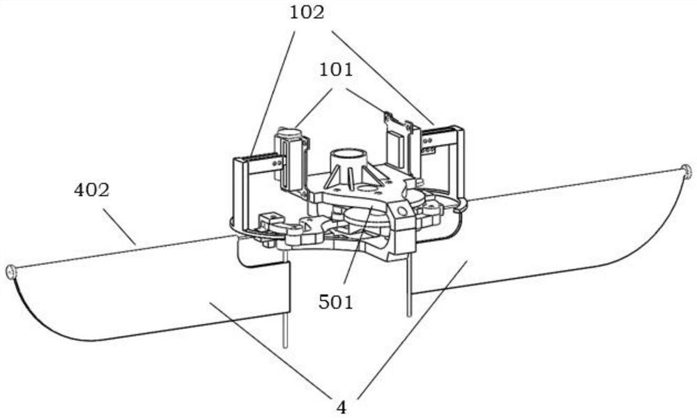
[0043] Such as figure 1 As shown, a bionic micro-flapperator lift and a roller torque control method of the present invention, the rolling control mechanism 1 of the aircraft includes a linear steering machine 101 and a control output mechanism 102, the linear steering machine 101 fixed On the upper base 501, the control output mechanism 102 is shown from the side surface, from the "T" shape from the view angle, and the upper end is fixed to the steering wheel of the linear steering machine 101, the bottom is one Horizontal circular ring block, the ring angle is greater than the mapping of the leading edge woff rod 402, which is used to ensure that the front foil wing rod 402 is subjected to the slave plane of the flaunt 4. Change. When the linear steering machine 101 does not require the rolling torque, the position of the control leading edge w...


PUM


Abstract

The invention discloses a lift force and rolling moment control method for a bionic micro flapping-wing aircraft, and aims to solve the problems of generation and control of lift force and rolling moment of the aircraft. When the aircraft needs to generate lift force and rolling torque, the deflection angles of wing rods at the front edges of flapping wings on the two sides around wing roots are controlled through steering engines, the flapping plane positions of the wings and the tightness degree of wing membranes are changed, then the lifting force of the wings is changed, the left side and the right side generate different lift force, and expected rolling torque is obtained; the rolling control of the bionic micro flapping-wing air vehicle is realized. According to the lift force and rolling control method, wings of the bionic micro flapping-wing aircraft are directly operated, a control mechanism is easy to implement, large deformation of a wing membrane can be caused by controlling movement of a leading edge wing rod, large control torque is generated, and in addition, the control mode that the two wings are controlled through the two steering engines respectively is adopted, so that the lift force and rolling speed is greatly improved. And the generation and control precision of the lift force and the rolling moment is also obviously improved.

Description

Technical field [0001] The present invention relates to the field of micro aircraft, in particular a bionic micro-flapping aircraft lift and a rolling moment control method. Background technique [0002] The micro aircraft is a new type of aircraft developed mid-1990s. In the past two decades, with the continuous improvement of traditional aircraft design technology and the continuous maturity of microelectronics technology, micro aircraft was proposed and rapidly developed. The micro aircraft has a small size, light weight, and good concealment. There is a wide range of application prospects in military and civilians such as reconnaissance, communications, exploration and assistance. [0003] As an important branch of a micro aircraft, bionic micro-flapping aircraft, with the development of bionic design, becomes a hot point in the field of miniature aircraft. The bionic miniature puff aircraft has a bionic shape that borrows the biological flight principle, and the gas dynamism...

Claims


Application Information

Patent Timeline
Patent Type & Authority Applications(China)
IPC IPC(8): B64C33/02
CPCB64C33/02
Inventor 吴江浩曹赫宇程诚
Owner BEIHANG UNIV
Why Eureka
Try Eureka