Eureka AIR delivers breakthrough ideas for toughest innovation challenges, trusted by R&D personnel around the world.

Pneumatic oil absorber with filtering, layering and driving adjustment functions

A technology of oil absorber and layering device, which is applied in the direction of filtration separation, fixed filter element filter, separation method, etc., and can solve problems such as easy pollution of the environment, troublesome movement, waist strain, etc.

Pending Publication Date: 2022-03-01
春秋航空技术发展江苏有限公司
View PDF0 Cites 0 Cited by
  • Summary
  • Abstract
  • Description
  • Claims
  • Application Information

AI Technical Summary

Problems solved by technology

[0003] The object of the present invention is to address the deficiencies of the prior art, to provide a pneumatic oil absorber with filter stratification and drive adjustment, so as to solve the problem of waste oil and Other impurities are sucked into the barrel at the same time, causing the waste oil inside the barrel to be discharged or the impurities in the waste oil need to be filtered during the use of other purposes. Because the impurities are soaked in the waste oil, it will not only cause the second generation of waste oil The reduction of secondary use value also causes the situation that impurities are easily polluted when they are discharged on the ground. At the same time, the existing pneumatic oil absorbers are all moved by the operator's hand, which not only causes troublesome movement during the working process of the overall pneumatic oil absorber It also increases the work intensity of the operator to move the pneumatic oil absorber. In the working process of the existing pneumatic oil absorber, the operator manually holds the oil suction pipe to bend over, which causes the problem that the operator is prone to waist strain during the long-term bending process.

Method used


Image

  • Pneumatic oil absorber with filtering, layering and driving adjustment functions
  • Pneumatic oil absorber with filtering, layering and driving adjustment functions
  • Pneumatic oil absorber with filtering, layering and driving adjustment functions

Examples


Embodiment Construction

[0037] The following will clearly and completely describe the technical solutions in the embodiments of the present invention with reference to the accompanying drawings in the embodiments of the present invention. Obviously, the described embodiments are only some, not all, embodiments of the present invention. Based on the embodiments of the present invention, all other embodiments obtained by persons of ordinary skill in the art without making creative efforts belong to the protection scope of the present invention.

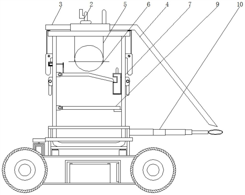
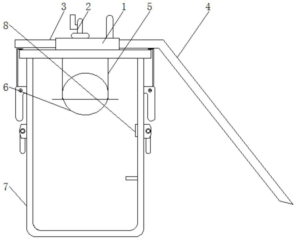
[0038] see Figure 1-8 , the present invention provides a technical solution: a pneumatic oil absorber with filter stratification and drive adjustment, such as figure 1 As shown, the top of the barrel cover 1 is inlaid with a compressed air joint 2, and one side of the top of the barrel cover 1 is inlaid and fixed with one end of the compressed air outlet pipe 3, and at the same time, the other side of the top of the barrel cover 1 is inlaid and fixed with one...


PUM


Abstract

The invention discloses a filtering layering and driving adjusting pneumatic oil suction device which comprises a barrel cover, a barrel body and a filtering layering device, a compressed air connector is embedded in the upper portion of the barrel cover, a lifting ring set is installed on the other side of the upper portion of the barrel cover, and an oil suction device head assembly is installed below the barrel cover. An automatic anti-overflow device is installed on the lower portion in the oil extractor head assembly, a clamping block is installed on one side of the lower portion in the barrel body, a limiting block is installed below the clamping block, movable rings are fixed to the two sides of the barrel body, movable buckles are fixed to the two sides of the barrel body, and meanwhile the barrel body is connected with the barrel cover through the movable buckles. The barrel body is installed above the driving steering device, the pneumatic oil absorber with the filtering, layering, driving and adjusting functions is provided with a movable buckle, the fixed connection effect is achieved through the movable buckle, and the locking connection effect on the barrel cover and the barrel body is achieved through the movable buckle; and meanwhile, the barrel cover and the barrel body are tightly and hermetically connected through the movable buckle.

Description

technical field [0001] The invention relates to the technical field of pneumatic oil absorbers, in particular to a pneumatic oil absorber with layered filtration and drive adjustment. Background technique [0002] Pneumatic oil absorbers are generally used to collect a variety of waste oils produced by aviation maintenance operations. The strong suction can collect liquids, corresponding small metal debris and small metals, etc., while the existing pneumatic oil absorbers will waste oil during work. Inhaled into the barrel together with other impurities, causing the waste oil inside the barrel to be discharged or the impurities in the waste oil need to be filtered during the use of other purposes, because the impurities are soaked in the waste oil, which not only causes waste oil The reduction in the value of secondary use also causes the pollution of the environment when impurities are discharged on the ground. At the same time, the existing pneumatic oil absorbers are all ...

Claims


Application Information

Patent Timeline
Patent Type & Authority Applications(China)
IPC IPC(8): F04B53/00F04B53/16F04B53/20B01D29/11B01D29/96
CPCF04B53/00F04B53/16F04B53/20B01D29/11B01D29/96
Inventor 张恺金钰蒋京涛
Owner 春秋航空技术发展江苏有限公司
Why Eureka
Eureka Blog
Learn More