
Hydraulic static pile driver and hydraulic control system thereof

A hydraulic control system and control valve technology, which is applied to fluid pressure actuators, mechanical equipment, servo motors, etc., can solve problems such as lifting, unfavorable equipment efficiency, and large energy waste

Pending Publication Date: 2022-03-01
SUNWARD INTELLIGENT EQUIP CO LTD
View PDF0 Cites 1 Cited by
  • Summary
  • Abstract
  • Description
  • Claims
  • Application Information

AI Technical Summary

Problems solved by technology

[0003] When the hydraulic system in the prior art is under fast pressure conditions, the oil returned from the small chamber of the oil cylinder first passes through the long pipeline, then passes through the fast pressure connection inside the multi-way valve, and then returns to the large chamber of the oil cylinder through the long pipeline, resulting in relatively large pressure loss. High, large energy waste, not conducive to the improvement of equipment efficiency

Method used


Image

  • Hydraulic static pile driver and hydraulic control system thereof
  • Hydraulic static pile driver and hydraulic control system thereof
  • Hydraulic static pile driver and hydraulic control system thereof

Examples


Embodiment Construction

[0052] The following will clearly and completely describe the technical solutions in the embodiments of the present invention with reference to the accompanying drawings in the embodiments of the present invention. Obviously, the described embodiments are only some, not all, embodiments of the present invention. Based on the embodiments of the present invention, all other embodiments obtained by persons of ordinary skill in the art without making creative efforts belong to the protection scope of the present invention.

[0053] The core of the present invention is to provide a hydraulic control system, which can realize the integrated setting of the control valve and the hydraulic pipeline, thereby simplifying the layout of the pipeline, reducing the labor intensity of operation, reducing energy consumption and improving work efficiency. Another core of the present invention is to provide a hydraulic static pile driver including the above-mentioned hydraulic control system.

...


PUM


Abstract

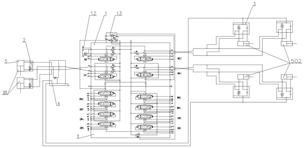
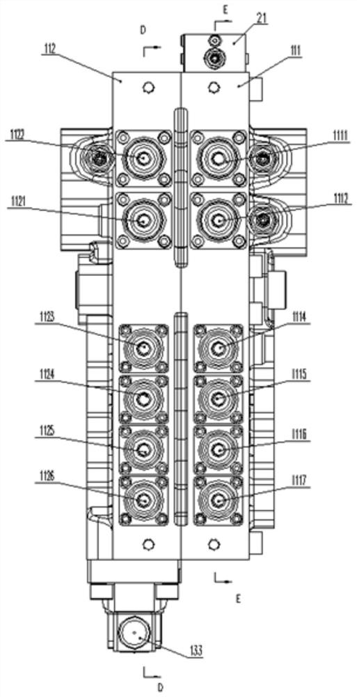
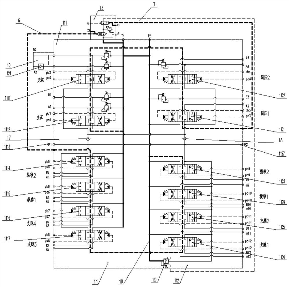
The invention discloses a hydraulic static pile driver and a hydraulic control system thereof.The hydraulic control system comprises a multi-way valve main valve, a fast pressure valve set, a fast return valve set, a main pressure oil cylinder and an auxiliary pressure oil cylinder, the fast pressure valve set is integrally arranged on the main pressure oil cylinder, and the fast return valve set is integrally arranged on the auxiliary pressure oil cylinder; the multi-way valve main valve is connected with the fast pressure valve set, and the multi-way valve main valve is connected with the fast return valve set. According to the hydraulic control system, the integrated arrangement of the multi-way valve main valve and the hydraulic valve group can be realized, so that the pipeline arrangement can be simplified, the operation labor intensity can be reduced, the energy consumption can be reduced, the working efficiency can be improved, the pressure grade of the system is high, and the high-pressure development requirement of equipment can be met.

Description

technical field [0001] The invention relates to the technical field of hydraulic control, in particular to a hydraulic control system. The invention also relates to a hydraulic static pile driver with the hydraulic control system. Background technique [0002] Hydraulic static pile driver is widely used foundation construction equipment, its core hydraulic control components include multiple manual multi-way control valves such as piling multi-way valve, travel multi-way valve, outrigger multi-way valve, confluence valve group, discharge Multiple decentralized control valve groups such as oil valve group. [0003] When the hydraulic system in the prior art is under fast pressure conditions, the oil return from the small cavity of the cylinder first passes through the long pipeline, then passes through the internal fast pressure connection of the multi-way valve, and then returns to the large cavity of the cylinder through the long pipeline, resulting in relatively large pre...

Claims


Application Information

Patent Timeline
IPC IPC(8): F15B11/16F15B13/06F15B13/02
CPCF15B11/16F15B13/06F15B13/02
Inventor 陈桂芳曾素赵金生
Owner SUNWARD INTELLIGENT EQUIP CO LTD
Learn More