Ignition structure of ignition gun and ignition gun

A technology of ignition gun and igniter, which is applied in the direction of combustion ignition, igniter with fuel, combustion method, etc., can solve problems such as ignition of the ignition gun, and achieve the effects of reducing ignition, safe carrying, and convenient touch

Pending Publication Date: 2022-03-01
NINGBO HUANHAI ELECTRIC APPLIANCES
View PDF7 Cites 0 Cited by
  • Summary
  • Abstract
  • Description
  • Claims
  • Application Information

AI Technical Summary

Problems solved by technology

[0005] In order to improve the problem of ignition of the ignition gun caused by false touch, the application provides an ignition structure of the ignition gun and an ignition gun

Method used


Image

  • Ignition structure of ignition gun and ignition gun
  • Ignition structure of ignition gun and ignition gun
  • Ignition structure of ignition gun and ignition gun

Examples


Embodiment Construction

[0043] The following is attached Figure 1-7 The application is described in further detail.

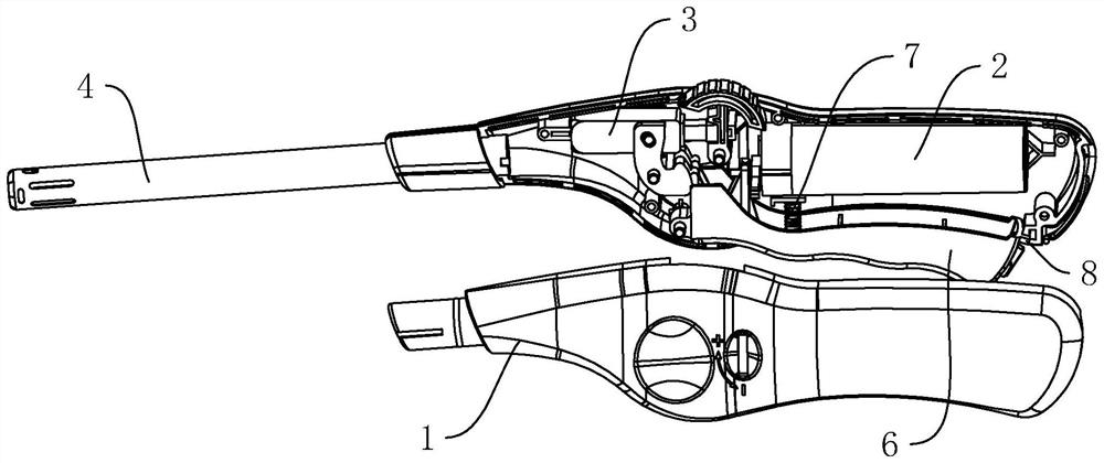
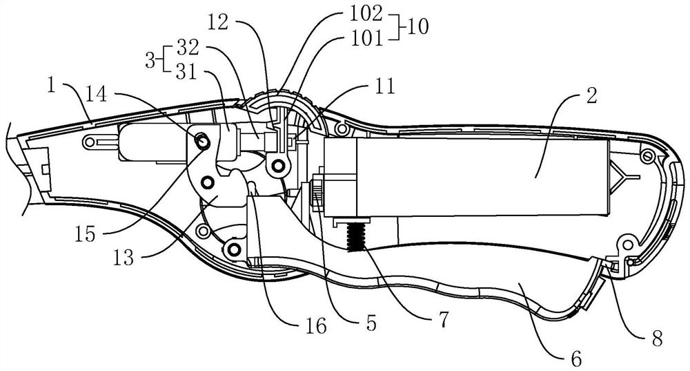
[0044] The embodiment of the present application discloses an ignition gun ignition structure, such as figure 1 As shown, it includes a casing 1 , an air box 2 and a piezoelectric igniter 3 . The housing 1 is formed by splicing two half-covers. The housing 1 has an accommodating cavity. The housing 1 is connected with an ignition gun barrel 4, and the ignition gun barrel 4 communicates with the accommodating cavity.

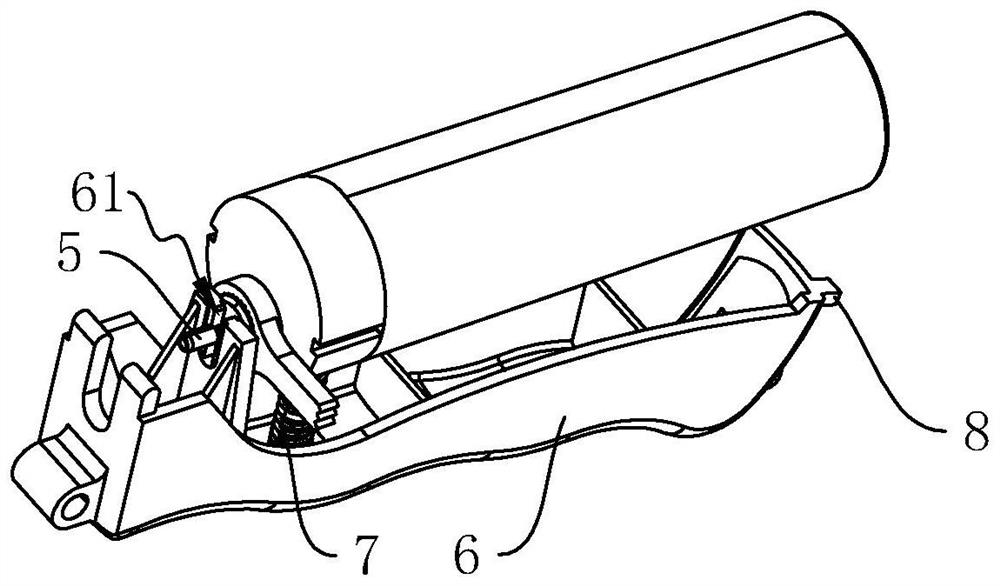
[0045] see figure 1 and figure 2The air box 2 is installed in the accommodation cavity. In order to fix the position of the air box 2, a plurality of positioning plates are arranged in the accommodation cavity, and the air box 2 is fixed in the accommodation cavity by the positioning plates touching the outer wall of the air box 2. Gas box 2 is connected with gas outlet valve 5, and gas outlet valve 5 is arranged toward the direction of firing gun barrel 4. Gas ou...


PUM


Abstract

The ignition structure comprises a shell, the shell is provided with a gas box, the gas box is connected with a gas outlet valve, the end, away from the gas box, of the gas outlet valve is used for being connected with a gas pipe, the shell is further provided with a piezoelectric igniter, the piezoelectric igniter is used for ignition, and the shell is further provided with a control piece. The control piece is movably connected to the shell and used for controlling the air outlet valve to be opened, and the shell is further movably connected with an ignition trigger which is used for controlling the piezoelectric igniter to be used for ignition. The control piece and the ignition trigger are arranged and need to be matched, so that the ignition condition caused by mistaken touch in the carrying process is reduced, and carrying is safer.

Description

technical field [0001] The present application relates to the field of igniters, more specifically, it relates to an ignition structure of a igniter and an igniter. Background technique [0002] The ignition gun is an electronic ignition device that uses flammable gases such as butane gas and natural gas. It is used in gas stoves, picnics and various occasions that require ignition in daily life. [0003] In the related technology, the ignition gun has an ignition trigger. When ignition is required, the outlet valve is opened by pulling the ignition trigger. At the same time, the piezoelectric ignition device generates an electric spark at the nozzle of the ignition gun through a wire. The combustible gas delivered to the mouth of the ignition gun, at this time, can maintain the burning flame at the mouth of the gun barrel. [0004] In view of the above-mentioned related technologies, the inventor believes that when the above-mentioned ignition gun is carried, there is a si...

Claims


Application Information

Patent Timeline
Patent Type & Authority Applications(China)
IPC IPC(8): F23Q2/16F23Q2/28F23Q2/34
CPCF23Q2/16F23Q2/287F23Q2/34
Inventor 胡棉飞罗劼桑华军
Owner NINGBO HUANHAI ELECTRIC APPLIANCES
Why Eureka
Try Eureka