Composite armor structure with inverted cone, manufacturing method and mounting method

A cone and armor technology, applied in the field of composite armor structure, can solve the problems of overall protection of unfavorable structures, and achieve the effect of reducing damage to the wound surface, convenient use, and smooth structure surface

Pending Publication Date: 2022-03-01
JIANGSU UNIV OF SCI & TECH
View PDF11 Cites 0 Cited by
  • Summary
  • Abstract
  • Description
  • Claims
  • Application Information

AI Technical Summary

Problems solved by technology

For example, in patent CN109178195A, a number of oblique ribs parallel to each other are evenly distributed on the inside of the upper panel and the lower panel. Although the impact direction of the projectile can be changed to a certain extent, the parallel ribs can only make the projectile deflect to one side, which is not conducive to the structure. The overall protection; the ribs of the protective plate are wrapped by the core material, which will restrain the deflection of the projectile to a certain extent, and cannot maximize the deflection effect of the projectile
[0007] It can be seen from the above that although the current composite armor structures have various types and functions, there are still many limitations and shortcomings in each technical solution.

Method used


Image

  • Composite armor structure with inverted cone, manufacturing method and mounting method
  • Composite armor structure with inverted cone, manufacturing method and mounting method
  • Composite armor structure with inverted cone, manufacturing method and mounting method

Examples


Embodiment 1

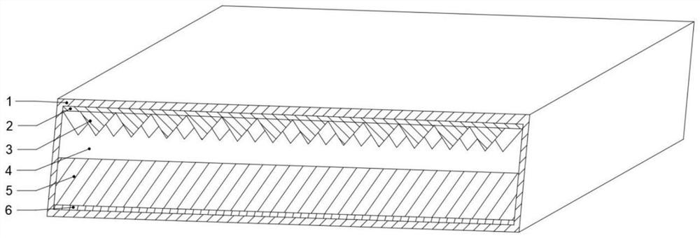
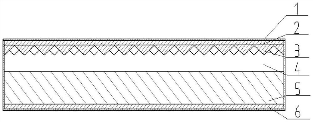
[0052] Such as figure 1 with figure 2 As shown, the composite armor structure with an inverted cone in this embodiment 1 includes a packaging shell 1, an upper panel 2, a cone 3, a gap layer 4, a kinetic energy absorbing layer 5 and a lower panel 6, such as Figure 4 As shown, the cones 3 are quadrangular pyramids, the rows of the cones 3 are misplaced, and the upper panel 2 and the cones 3 form an integrated structure through mold casting. The kinetic energy absorbing layer 5 is embedded in the package shell by the finished product, the connection mode of the upper panel 2 and the package shell 1, the connection mode of the kinetic energy absorbing layer 5 and the lower panel 6, and the connection mode of the lower panel and the package shell 1 can be glued and sealed in the package shell 1 The inner cavity fits into the groove and is limited by the first stopper 102 and the second stopper 103, so that the unit structures of the armor structure are combined to form a whole....

Embodiment 2

[0059] Such as figure 2 with Figure 4 As shown, the composite armor structure with an inverted cone in this embodiment 2 includes a package shell 1, an upper panel 2, a cone 3, a gap layer 4, a kinetic energy absorbing layer 5 and a lower panel 6, wherein the cone is a square pyramid, The cones 3 are misplaced between rows, and the upper panel 2 and the cones 3 form an integrated structure through mold casting. The kinetic energy absorbing layer 5 is embedded in the package shell by the finished product, the connection mode of the upper panel 2 and the package shell 1, the connection mode of the kinetic energy absorbing layer 5 and the lower panel 6, and the connection mode of the lower panel and the package shell 1 can be glued and sealed in the package shell 1 The inner cavity fits into the groove and is limited by the first stopper 102 and the second stopper 103, so that the unit structures of the armor structure are combined to form a whole.

[0060] The package shell ...

Embodiment 3

[0062] Such as figure 2 with Figure 5 As shown, the composite armor structure with an inverted cone in this embodiment 3 includes a packaging shell 1, an upper panel 2, a cone 3, a gap layer 4, a kinetic energy absorbing layer 5 and a lower panel 6, wherein the cone is a cone, and the cone The bodies 3 are misplaced between rows, and the cones 3 are formed by machining on the surface of the upper panel 2 . The kinetic energy absorbing layer 5 is embedded in the package shell by the finished product, the connection mode of the upper panel 2 and the package shell 1, the connection mode of the kinetic energy absorbing layer 5 and the lower panel 6, and the connection mode of the lower panel and the package shell 1 can be glued and sealed in the package shell 1 The inner cavity fits into the groove and is limited by the first stopper 102 and the second stopper 103, so that the unit structures of the armor structure are combined to form a whole.

[0063] Among them, the packagi...


PUM


Abstract

The composite armor structure comprises an upper panel, the cone located on the lower surface of the upper panel, a lower panel, a kinetic energy absorption layer located on the upper surface of the lower panel and a packaging shell wrapping the periphery, the upper panel and the cone are of an integrally-formed structure, and the cone head faces the lower panel; a gap layer used for guaranteeing sufficient deflection of a penetration body is arranged between the kinetic energy absorption layer and the cone of the upper panel in a spaced mode. According to the armor structure of the combined bulletproof mechanism of yaw induction, gap deviation promotion and tail end energy absorption, a cone arranged downwards starts to induce a missile body to yaw, and a gap layer is arranged in the middle to amplify the yaw so as to further promote a trajectory to completely yaw and increase the stress area; finally, a kinetic energy absorbing layer is arranged to prolong a projectile body path and effectively absorb residual kinetic energy of the projectile body.

Description

technical field [0001] The invention relates to an armor structure suitable for armor protection and ship building, in particular to a composite armor structure with an inverted cone, a manufacturing method and an installation method. Background technique [0002] In the prior art, a lot of research has been carried out on the phenomenon of high-speed penetration, so as to reduce the damage of the protected structure and resist the penetration of high-speed projectiles. With the continuous development of technology and the improvement of protection requirements, the impact resistance of traditional homogeneous armor represented by a single metal is far from meeting the demand, so various new composite materials and composite armor structures continue to emerge. [0003] Composite armor structure is a heterogeneous protective structure composed of more than two layers of protective materials with different properties. It can be mainly divided into three categories: metal and ...

Claims


Application Information

Patent Timeline
Patent Type & Authority Applications(China)
IPC IPC(8): F41H5/04F41H5/013B63G13/00B32B15/20B32B15/18B32B15/04B32B27/40B32B27/34B32B15/088B32B15/095B32B3/04B32B3/08B32B7/08
CPCF41H5/0442F41H5/013B63G13/00B32B15/20B32B15/18B32B15/043B32B3/085B32B27/40B32B27/34B32B15/088B32B15/095B32B3/04B32B3/08B32B7/08B32B2571/02B32B2307/304B32B2307/102B32B2307/56B32B2307/558B32B2307/718B32B2605/12B32B2605/00
Inventor 刘畅陈墨林樊乐秦珮雯夏志平陈豪杰沈超明
Owner JIANGSU UNIV OF SCI & TECH
Why Eureka
Try Eureka