Eureka AIR delivers breakthrough ideas for toughest innovation challenges, trusted by R&D personnel around the world.

Auto-collimator

An autocollimator and multi-slit technology, which is applied in the direction of instruments, measuring devices, optics, etc., can solve problems such as limited applications, and achieve the effect of improving subdivision accuracy, improving stability, and reducing optical components

Active Publication Date: 2022-03-01
CHANGCHUN INST OF OPTICS FINE MECHANICS & PHYSICS CHINESE ACAD OF SCI
View PDF6 Cites 0 Cited by
  • Summary
  • Abstract
  • Description
  • Claims
  • Application Information

AI Technical Summary

Problems solved by technology

However, the autocollimator of this method emits converging light, and the measured surface needs to be at a certain distance from the autocollimator, which limits the application of this method in other occasions

Method used


Image

  • Auto-collimator
  • Auto-collimator
  • Auto-collimator

Examples


Embodiment Construction

[0028] Embodiments of the present invention will be further described in detail below in conjunction with the accompanying drawings and examples. It should be noted that, in the case of no conflict, the embodiments of the present invention and the features in the embodiments can be combined with each other. Based on the embodiments of the present invention, all other embodiments obtained by persons of ordinary skill in the art without creative efforts fall within the protection scope of the present invention.

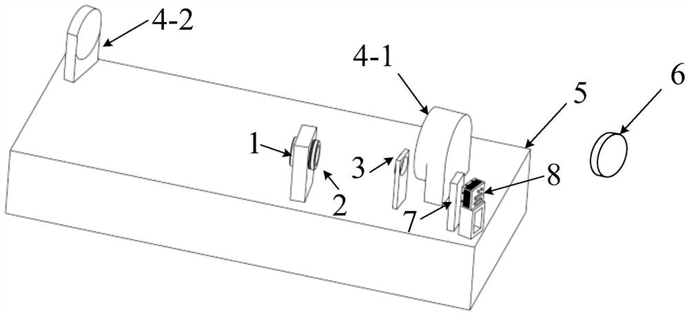
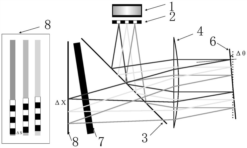
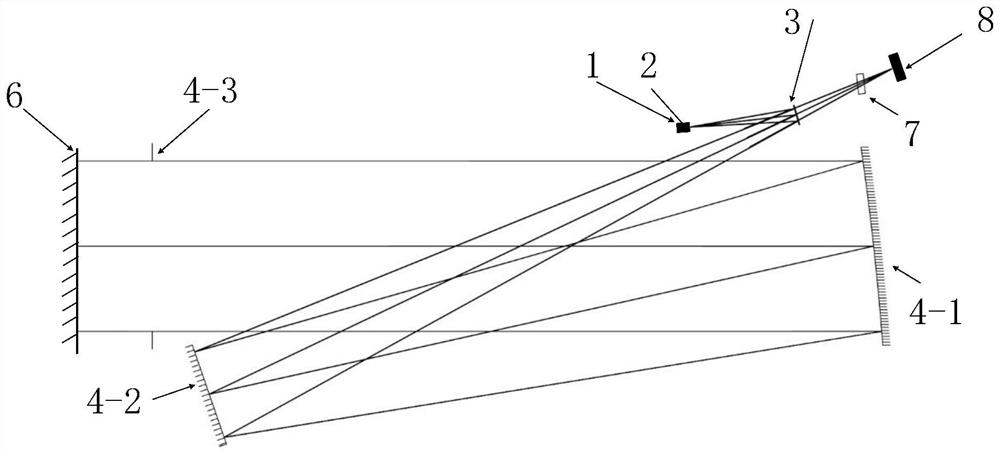
[0029] figure 1 A schematic diagram of the three-dimensional structure of the autocollimator in the embodiment of the present invention is shown. figure 2 A schematic diagram of the first principle of the autocollimator in the embodiment of the present invention is shown. image 3 A schematic diagram of the second principle of the autocollimator in the embodiment of the present invention is shown.

[0030] Such as Figure 1-Figure 3 As shown, the embodiment of the ...


PUM

PropertyMeasurementUnit
thicknessaaaaaaaaaa
thicknessaaaaaaaaaa

Abstract

The invention provides an autocollimator, which comprises a light source, a multi-slit reticle, a spectroscope and a photoelectric detector which are arranged on a base and are sequentially arranged along a light path, and also comprises a collimator and a dispersion element which are arranged on the base and are sequentially arranged along the light path, a light beam emitted by the light source enters the multi-slit reticle and is divided into N light beams through the multi-slit reticle, the N light beams enter the spectroscope, the N light beams are reflected to the collimator through the spectroscope to form N parallel light beams, the N parallel light beams enter the reflector to be measured, and the reflector to be measured is measured through the spectroscope. And a light beam reflected by the reflector to be measured is transmitted to the dispersion element through the collimator and the spectroscope in sequence, is refracted by the dispersion element and then enters the photoelectric detector for imaging, the imaging offset is obtained, and the offset angle of the reflector to be measured is further obtained.

Description

technical field [0001] The invention belongs to the technical field of measurement and testing of geometric quantities, and in particular relates to an autocollimator. Background technique [0002] In the field of ultra-high-precision measurement, there is an urgent need for ultra-high-precision angle measurement in free-form surface detection, ultra-high-precision weak force measurement, etc., especially in the mHz frequency band, where the accuracy of angle measurement is about 1 order of magnitude lower than that of high-frequency (10Hz) , it is more difficult to improve the accuracy. The autocollimator uses the principle of optical self-collimation to emit parallel light through the telescope, and the parallel light fed back by the measured target returns to the telescope to form an image on the target surface. The image distance is measured by the photodetector to obtain high-precision angle information. How to improve resolution and stability is the development direct...

Claims


Application Information

Patent Timeline
Patent Type & Authority Applications(China)
IPC IPC(8): G01B11/26G02B27/30
CPCG01B11/26G02B27/30
Inventor 王智朱俊青方超王永宪
Owner CHANGCHUN INST OF OPTICS FINE MECHANICS & PHYSICS CHINESE ACAD OF SCI
Why Eureka
Eureka Blog
Learn More