[0027] The technical solutions in the embodiments of the present invention will be described in conjunction with the accompanying drawings in which the drawings in the embodiments of the present invention will be apparent from the embodiments of the present invention. Based on the embodiments of the invention, all other embodiments obtained by those of ordinary skill in the art without performing creative labor premises.
[0028]It should be noted that all directional indications (such as above, lower, left, right, front, and then ...) are only used to explain the relatives between the components in a particular attitude (as shown in the drawings). Location relationship, exercise situation, etc. If the specific posture changes, the directional indication is also changed accordingly.
[0029] Further, in the present invention, "first", "second", and the like are intended to be intended to describe purposes only, and cannot be understood as an indication or implies its relative importance or implicitly indicated the number of technical features indicated. Thus, the features of "first", "second" are defined, and at least one of the features may be indicated or implicitly. In addition, the technical solution between the various embodiments can be combined with each other, but it must be based on those of ordinary skill in the art. When the combination of the technical solution occurs or cannot be realized, the binding of this technical solution does not exist. It is not within the scope of the claims of the present invention.
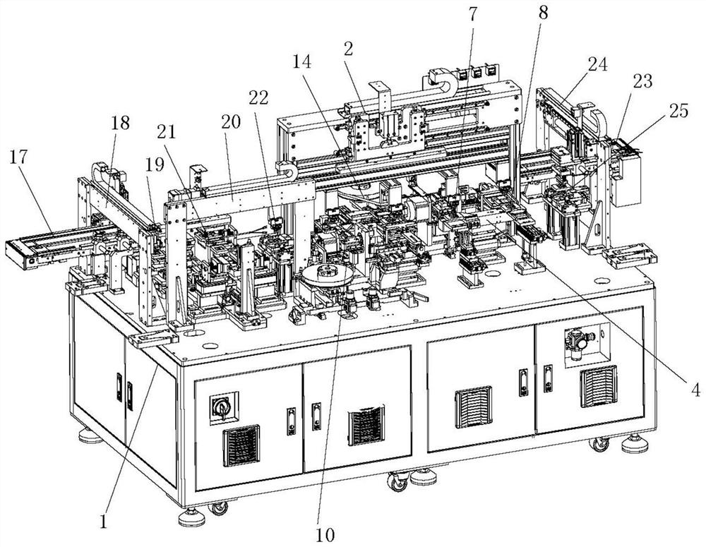
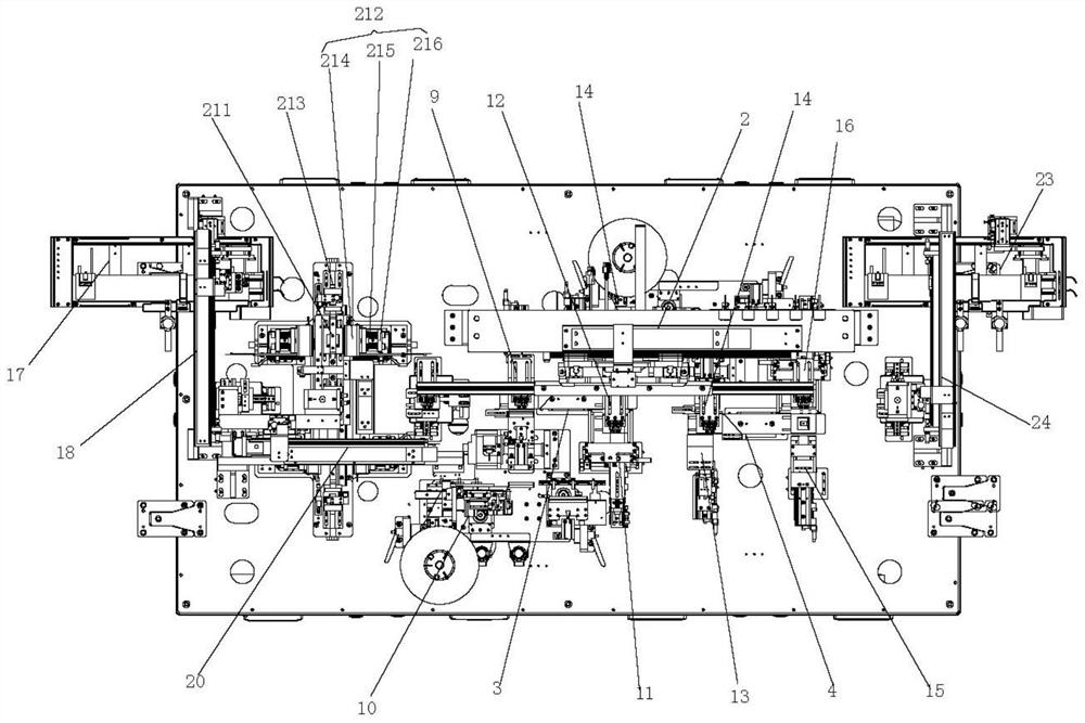
[0030] Such as figure 1 As shown, a shaping machine is stored on both sides of the cell, including a machine, and a linkage robot 2, a front side surface adhesive electrical core support table 3 and a rear side gel electrical core support station 4, front side gel The electrical core support table 3 is provided with a front side gelatin positioning station 5 and a front rolling station 6, and a rear side gel cell support station 4 is provided with a rear side gelatin positioning station 7 and a rear side rollometer. Bit 8, the machine 1 is located on one side of the front side gelatin positioning station 5 with a front gelatin positioning mechanism 9, and the machine table 1 is located on the other side of the front side gelatin positioning station 5. The glue module 10, the machine 1 is provided on one side of the front side rolling station 6 is provided with a front wrapper push electrical core mechanism 11, and the machine table 1 is located on the other side of the front side rolling station 6. The roller wrap mechanism 12 is provided on one side of the rear side gelatin positioning station 7, and the machine table 1 is provided on the other side of the rear side gelatin positioning station 7. The rear intercepting glue module 14, the machine 1 is located on one side of the rear rollometer station 8, and the back wrap is provided on the other side of the back side roll stickers 8 on the back side. It is provided with a rear roller wrap mechanism 16.
[0031] The handling process of the linkage robot 2 is to sequentially position the product from the second excessive positioning station 5, the front side glue positioning station 6, the rear side gelatin positioning station 7, the rear side roll center Bit 8 to the third excess positioning station 25.
[0032] Preferably, the feed end of the machine 1 is provided with a feed line 17, a superbly mechanical hand 18, a first excessive positioning station 19, a two-fun engaging mechanism 20, a heat shaping mechanism 21, and a second excess positioning station 22, a sheet. The robot 18 takes from the feed pipeline 17 and carries the product to the position of the first excessive positioning station 19, and one of the two-stage mechanism 3 is sucks the product on the first excessive positioning station 19, and The product on the suction cup absorbs the thermal shaping mechanism 21, the two-moving mechanism hand 20 transports the product on the first excess position 19 to the heat shaping mechanism 21 for hot press shaping, the two funnel mechanism 21 is hot on the heat shaping mechanism 21 The pressure-shaped product is transported to the second excess positioning station 22 for secondary positioning.
[0033] The thermal shaping mechanism 21 includes an intermediate positioning platform 211, and a hot pressing mechanism 212 is provided on both sides of the intermediate positioning platform 211, and one end of the intermediate positioning platform 211 is provided with a push-electric cord gas cylinder 213. The push-core gas cylinder 213 is pushed. The thermal integrated battery is positioned on the secondary positioning platform. The heat pressing mechanism 212 includes a pressing cylinder, a pressing cylinder controls a slide plate movement, and a hot press plate 214 is provided on the sliding plate, and a spring mounting rod is provided on one side of the hot press plate 214, and a spring mounting rod is provided with a cushion spring 215. The other end of the spring mounting rod is attached to the fixing plate 216, and the fixing plate is mounted on the slide plate. The pressing cylinder 212 drives the slide plate to move the heat pressing plate 214 hot pressing die side, and the buffer spring 215 can buffer the pressure relief to prevent the electrical cell deformation or surface damage.
[0034] Preferably, the discharge end of the machine 1 is provided with a lower generating line 23, a sheet robot 24, and a third over-positioning station 25, and the linkage robot 2 will be transported to the rear rollometer 8 has been transported. The third excess positioning station 25 is positioned, and the charger hand 24 carries the product on the third excess positioning station 25 to the lower current water wire 23. The lower assembly line 23 passes the sensor induction battery, and the signal is given to the positioning cylinder and the feed motor, the positioning cylinder is released, and the feed motor starts the conveying cell.
[0035] Both the feed pipeline 17 and the lower flow water wire 23 employ the conveying belt transport method, by which the conveyor belt cycle is rotated by the feed motor, when the battery cell is delivered to the specified position, by the sensor sense cell, the signal is given the positioning cylinder and The feed motor, the feed motor stops delivery, the electrical core positioning cylinder operates the battery cell, and the electrical core can be taken.
[0036] The upper robot 18 and the blanket robot 24 each include a gantry profile bracket, a rod transmission mechanism on a gantime profile holder, a screw drive control a lifting mechanism, and a lifting mechanism controls a lifting plate lifting (set up) Suction cup adsorption cell.
[0037] Preferably, the front intercept gum module 10 and the post-cut glue die group 14 each include a tape supply mechanism 101 and a flipping gelatin mechanism 102;
[0038] The tape supply mechanism 101 includes a mounting of the main seat 1011, and the hub 1012 is provided on the mounting main seat 1011, the rubber tape mechanism 1013, the rubber mechanism 1014, and the rubber tube adjustment motor 1014, and the plastic wheel 1012 is rotated by the rotary control cylinder. The hinges are provided with the output shaft of the regulating motor, and the rubber distance adjusting motor 1014 controls the movement of the truncated mechanism 1013 through the gear and the rack;
[0039] The truncated mechanism 1013 includes a moving plate 10131, and the moving plate 10131 is coupled to the mounting main seat 1011 by a linear slide and a linear block, and the moving plate 10131 is connected to the rack, and the moving plate 10131 is provided with an adhesive tumble cylinder 10132, The rubber cylinder 10133 and the claw cylinder 10134, the clarifier cylinder 10134 controls a trip-off cutter 10135 to trip the tape, and the compact cylinder 10133 controls the front and rear movement of the clarifier cylinder 10134, and the adhesive cylinder 10132 controls the left and right of the pressurized cylinder 10133. Move, the rubber belt mechanism 1013 includes a jaw cylinder 10136, and the jet tape cylinder 10136 is mounted on a bracket 10137, and the bracket 10137 is mounted on the moving plate 10131; the jet tape cylinder 10136 holds the tape, the rubber distance adjustment motor 1014 The gear and rack meshing drive control the jet belt mechanism 1013, the tape is also pulled out of the designated length;
[0040] The tape supply mechanism 101 also includes a pressure tape mechanism 1015, and the compact tape mechanism 1015 includes a pressure-glued head distance adjusting motor 10151, controlling the moving plate 10152 of the moving plate 10152 by the press-fit head distance adjusting motor 10151, and a pressure elongated cylinder is provided on the horizontal moving plate 10152. 10153, the piston rod end of the compact cylinder 10153 is provided with a pressurizing wheel mounting plate 10154, and one end of the pressure rubber wheel mounting plate 10154 is provided with a compressor wheel 10155. The compact tape mechanism 1015 can press the tape when the tape is adsorbed in the flip generking mechanism 102, so that the tape is stably adsorbed on the adsorption hole position on the flipping gelatin mechanism 102.
[0041] The flipping gelatin mechanism 102 includes a flip motor mounting bracket 1021, and a flip motor 1022 is provided on one side of the flip motor mounting bracket 1021, and the rotary rod 1023 is connected to the output shaft of the flip motor 1022, and the rotary bar 1023 is mounted on the rotary cylinder mounting plate. 1024, the adhesive cylinder 1025 and the suction plate 1026 are provided on the adhesive cylinder 1025, and the piston rod end of the adhesive cylinder 1025 is attached to one end of the suction rubber sheet 1026, and the other end of the suction rubber sheet 1026 is provided with an adsorbed hole.
[0042] Preferably, the front gelatin positioning mechanism 9 and the rear gelatin positioning mechanism 13 each include a pressure plate cylinder mount 91, and a pressure plate is close to the cylinder 92, and the pressure plate is close to the cylinder 92 controls the blocking cylinder 93 horizontally. The piston rod of the pressure plate cylinder 93 is connected to the upper and lower cylinder mounting plate 94, and one side of the upper and lower cylinder mounting plate 94 is provided with a core upper and lower air cylinder 95, and the piston rod end of the electric cylinder upper and lower air cylinder 95 is provided with a side positioning pressure plate 96.
[0043] Preferably, the front wrapper push electrical core mechanism 11 and the rear wrapping push electrical core mechanism 15 includes a push-to-drop base 111, and a push-electric core gas cylinder 112 is provided on the push core riser 111, and the electrical core cylinder 112 is provided. The piston rod end is provided with a push-to-core positioning plate 113, and a battery-core elastic push plate 114 is provided on one side of the pushing core positioning plate 113.
[0044] Preferably, the front roller gelatin mechanism 12 and the rear roller gelatin mechanism 16 each include a wrapper wheel to adjust the lifting gas cylinder 121, and the piston rod end of the wrap the rubber wheel adjusting the lifting cylinder 121 is provided with an annealing cylinder mounting plate 122, an retracted cylinder One side of the mounting plate 122 is fixedly mounted with a wrap-wrap-side retardation cylinder 123, and the rubber wheel side retracting cylinder 123 is provided with a spring plate assembly 124, and the piston rod end of the wrap the rubber wheel side retracting cylinder 123 is provided with a wrapper elastic clamp. The mounting bracket 125 is mounted, and the rubber elastic clamp mounting bracket 125 is provided with a wrap-forming elastic clamp 126, and the wrapping elastic clamp 126 includes an upper pinch 127 and a lower pinch plate 128, and one end of the upper splint 127 and the lower clamp 128 is provided with a wrap glue roller 129. The other end of the upper splint 127 and the lower pinch 128 is provided with a reset spring 120, and the other end of the reset spring 120 is connected to the wrap the elastic clamp mounting bracket 125;
[0045] The front wrapper push electrical core mechanism 11 and the rear wrapper push electrical core mechanism 15 push the battery between the upper splint 127 and the lower clamp 128, and the two wrap rubber roller 129 roll paper is pasted on the battery cell.
[0046] Preferably, the spring plate assembly 124 includes a mounting of the bottom plate 1241, and there is a straight rail 1241 having a straight rail and a linear slider, and one end of the mounting bottom plate 1241 is provided with a spring rod fixing plate 1242, and one side of the spring rod fixing plate 1242 is provided. The spring rod 1243 is provided with a spring 1244 on the spring rod 1243, and a connecting block 1245 is provided on the straight slider. The connecting block 1245 is provided with a side shot plate 1246, and one end of the side incident plate 1246 extends into the upper splint 127 and the lower. Between the pinch 128, the other end of the spring rod 1243 is connected to the connection block 1245, and when the core is pushed into the upper pinch plate 127 and the lower pinch plate 128, the top is on the side projectile plate 1246.
[0047] Preferably, the front side gelatin positioning station 5 and the rear side gelatin positioning station 6 are provided with front and rear positioning push plate cylinders 23, and the piston rod end of the push plate cylinder 23 is provided with a push plate 24, before On the other side of the lateral gelatin positioning station 5 and the rear side gelatin positioning 7, there is provided a gelatinous side rising positioning cylinder 25, and the piston rod end of the gelatin side rising positioning cylinder 25 is provided with an adhesive side rising baffle. 26. One end of the front side gelatin positioning station 5 and the rear side gelatin positioning station 6 is provided with a dielectric core abutment bit block 27, and the dielectric core can be positioned to locate the cell to prevent the battery.
[0048] Preferably, the linkage robot 2 and the two funnel mechanism hand 20 include a gantry bracket 201, and the gantry bracket 201 is provided with a traverse rod module 202, which controls the traverse rod module 202 to control the traversed air cylinder module 203, The lifting cylinder module 203 controls the upper and lower movement of the lifting mounting plate 204, and the bottom portion on the lift mounting plate 204 is connected to the adjustment board mounting profile 205, and the bottom interval of the adjustment plate mounting profile 205 is provided with a plurality of adjustment plates 206, each adjustment board 206 The suction cup 207 is provided, and each adjustment plate 206 is mounted on the adjustment plate mounting profile 205 by a waist hole dislocation.
[0049] The bottom interval of the adjustment plate mounting material 205 of the two-fastener mechanism 20 is provided with two adjusting plates 206, and both of the two adjusting plates 206 are provided with a suction cup 207, and five adjustment plate mounting profiles 205 of the linkage robot 2 is provided. The plate 206 is provided with a suction cup 207 on the five adjustment boards 206.
[0050]Although the embodiments of the present invention have been shown and described, those skilled in the art can be understood that these embodiments can be made, modified, and replaced without departing from the principles and structures of the present invention.And variations, the scope of the invention is defined by the appended claims and their equivalents.