Reactive power compensation device, method and system for power flow control device
A technology of power flow control and power compensation, applied in reactive power compensation, flexible AC transmission system, AC network voltage adjustment, etc., to maintain voltage stability and prevent overvoltage hazards.
- Summary
- Abstract
- Description
- Claims
- Application Information
AI Technical Summary
Problems solved by technology
Method used
Image
Examples
Embodiment 1
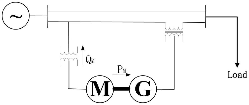
[0028] This embodiment introduces a reactive power compensation device for a power flow control device, including: a synchronous motor M, a synchronous motor G, a parallel transformer and a series transformer, and when one of the synchronous motor M and the synchronous motor G is a generator , and the other is a motor; the synchronous motor M is connected to the low-voltage side of the parallel transformer, and the high-voltage side of the parallel transformer is connected in parallel to the high-voltage line; the synchronous motor G is connected to the primary side of the series transformer, and the secondary side of the series transformer is connected to the high-voltage line.
[0029] Synchronous motor M and synchronous motor G are two coaxial synchronous motors whose magnetic field windings differ by 90 electrical degrees. The magnetic field winding of synchronous motor M is 90 electrical degrees ahead of the synchronous motor G magnetic field winding designed by this device...
Embodiment 2
[0035] This embodiment provides a control method for a reactive power compensation device for a power flow control device according to Embodiment 1, and its application process specifically involves the following steps:
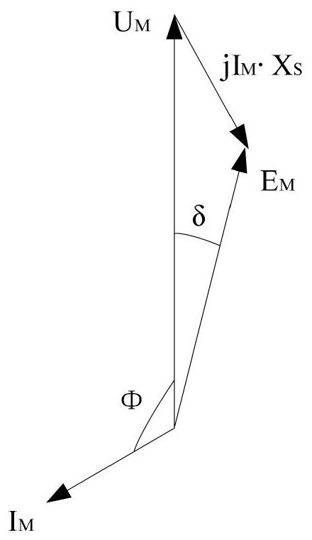
[0036] 1) In response to the need to increase the reactive power of the access point on the parallel side, issue a reactive power command to the synchronous motor M, rapidly increase the excitation current of the synchronous motor M, and make the electromotive force E of the synchronous motor M M The amplitude is greater than the motor port voltage U M , so that sufficient reactive power compensation can be provided to the system.
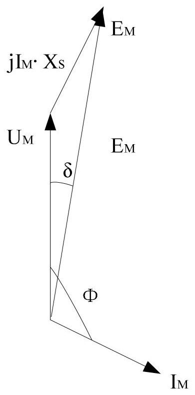
[0037] 2) In response to the excessive reactive power of the access point due to the overvoltage of the line caused by the over-compensation of the line itself or the high-voltage line empty / light load on the parallel side, an instruction to absorb reactive power is issued to the synchronous motor M. Rapidly reduce the excitation...
Embodiment 3
[0043] This embodiment provides a control system for a reactive power compensation device for a power flow control device according to Embodiment 1, including:
[0044] The excitation current control module of the synchronous motor M: in response to the need to increase the reactive power of the access point on the parallel side, send a reactive power command to the synchronous motor M, and rapidly increase the excitation current of the synchronous motor M. In response to the excess reactive power of the access point on the parallel side, an instruction to absorb reactive power is issued to the synchronous motor M, and the excitation current of the synchronous motor M is rapidly reduced.
[0045] The invention includes a two-stage synchronous motor, which has fault isolation capability and harmonic suppression capability, provides short-circuit capacity support and voltage support for the power grid through the ability of the synchronous motor M to absorb and generate reactive ...
PUM
 Abstract
Description
Claims
Application Information
 - R&D
- Intellectual Property
- Life Sciences
- Materials
- Tech Scout
- Unparalleled Data Quality
- Higher Quality Content
- 60% Fewer Hallucinations
Browse by: Latest US Patents, China's latest patents, Technical Efficacy Thesaurus, Application Domain, Technology Topic, Popular Technical Reports.
© 2025 PatSnap. All rights reserved.Legal|Privacy policy|Modern Slavery Act Transparency Statement|Sitemap|About US| Contact US: help@patsnap.com


