Power flow control device, method and system

A technology of power flow control and control method, which is applied in the direction of circuit devices, harmonic reduction devices, AC network circuits, etc., can solve problems such as line overload, grid harmonic pollution, and loss increase, and achieve voltage stability and power flow control. Effect

Pending Publication Date: 2021-06-04
NANJING NARI GROUP CORP +1
View PDF2 Cites 2 Cited by
  • Summary
  • Abstract
  • Description
  • Claims
  • Application Information

AI Technical Summary

Problems solved by technology

However, whether it is a multi-terminal DC transmission system or an AC transmission system, there is the problem of insufficient freedom of power flow control, which leads to line overload and increased loss.
The current power flow control scheme is basically power electronic equipment, which is easy to bring harmonic pollution to the power grid, so it is urgent to adopt new power flow control technology

Method used


Image

  • Power flow control device, method and system
  • Power flow control device, method and system
  • Power flow control device, method and system

Examples


Embodiment Construction

[0025] The present invention will be further described below in conjunction with the accompanying drawings. The following examples are only used to illustrate the technical solution of the present invention more clearly, but not to limit the protection scope of the present invention.

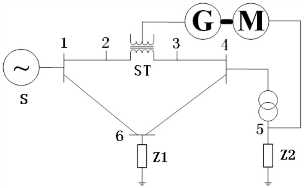
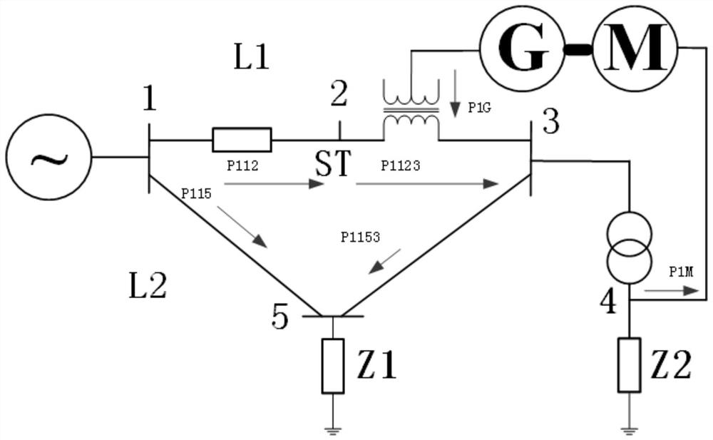
[0026] A power flow control device includes a synchronous motor M, a synchronous motor G, and a series transformer; the synchronous motor M is connected in parallel to the low-voltage side of a substation transformer, the synchronous motor G is connected to the primary side of the series transformer, and the secondary side of the series transformer is connected to the high-voltage side of the substation transformer.

[0027] Synchronous motor M and synchronous motor G are two coaxial synchronous motors whose magnetic field windings differ by 90 electrical angles. One is used as a motor and the other is used as a generator. Motors with conventional field control.

[0028] The capacity of the syn...


PUM


Abstract

The invention discloses a power flow control device, method and system. The device comprises a two-stage synchronous motor, has the fault isolation capability and harmonic suppression capability, provides short-circuit capacity support and voltage support for a power grid through the M suction and generation reactive power capability of the synchronous motor, and maintains the stability of the system voltage and the new energy grid-connected point voltage. The amplitude-adjustable voltage is output through the synchronous motor G and a series transformer, the equivalent impedance of a line is changed, and power flow control is achieved.

Description

technical field [0001] The invention relates to a power flow control device, method and system, and belongs to the technical field of power system stability and control. Background technique [0002] With the comprehensive promotion and application of UHV AC and DC transmission technology, the power grid is not only a traditional power transmission carrier, but also a powerful energy conversion, efficient configuration and interactive service platform. Through this platform, coal, hydropower, wind energy, solar energy , nuclear energy, biomass energy, tidal energy and other primary energy sources can be converted into electrical energy to achieve multi-energy complementarity, coordinated development, and rational utilization. Vigorously developing renewable energy is a practical and feasible way to solve the energy shortage in the world today. However, the problem of uneven distribution of renewable energy means that the generated electric energy needs to be transmitted to ...

Claims


Application Information

Patent Timeline
Patent Type & Authority Applications(China)
IPC IPC(8): H02J3/06H02J3/01H02J3/38H02J3/18H02J3/40
CPCH02J3/06H02J3/01H02J3/381H02J3/18H02J3/40H02J2203/10H02J2203/20H02J2300/20Y02E40/40Y02E40/30
Inventor 许其品杨玲
Owner NANJING NARI GROUP CORP
Why Eureka
Try Eureka