Control system, control method and rechargeable battery protection integrated circuit
A rechargeable battery and control system technology, applied in battery overcharge protection, battery overcurrent protection, battery circuit devices, etc., can solve problems such as voltage balance adjustment accuracy reduction
- Summary
- Abstract
- Description
- Claims
- Application Information
AI Technical Summary
Problems solved by technology
Method used
Image

Examples
no. 1 approach >
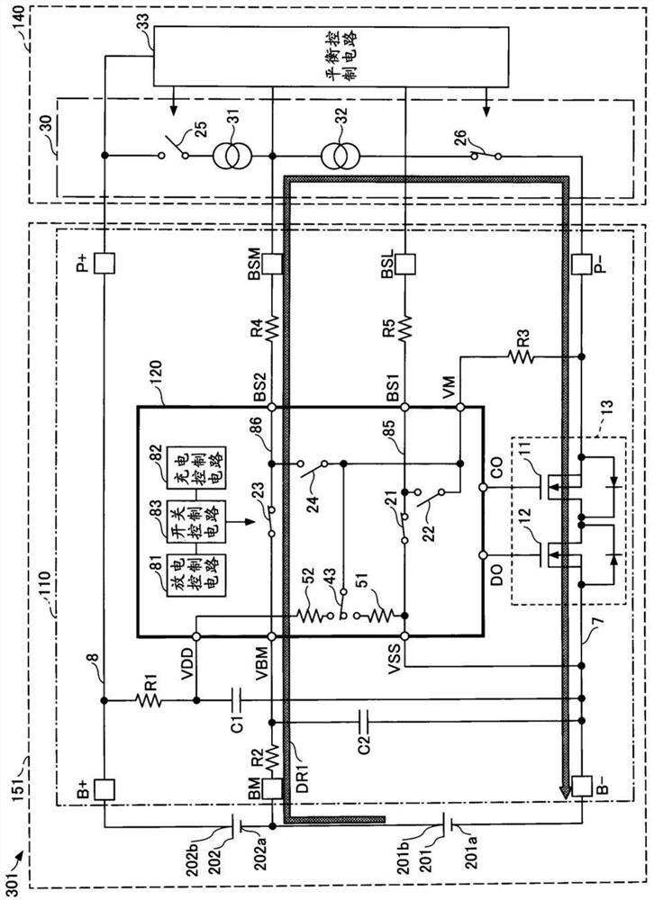
[0080] figure 1 It is a figure which shows an example of a structure of the control system in 1st Embodiment. figure 1 The control system 301 shown is a system which controls the balance of the cell voltage of each of the multiple (two in this example) rechargeable battery cells 201 and 202 connected in series. The control system 301 has an external device 140 and a battery pack 151 .
[0081] The external device 140 is a device connected to the battery pack 151 . The external device 140 may be a charger for charging the battery pack 151 , or may be a device that operates with electric power supplied from the battery pack 151 . Specific examples of devices that operate using electric power supplied from the battery pack 151 include electronic devices such as smartphones, tablet PCs, and mobile phones.
[0082] The external device 140 has a balance control circuit 33 that controls the balance of the cell voltages of the plurality of rechargeable battery cells. The balance c...
no. 2 approach >
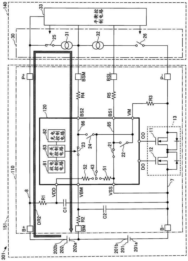
[0135] Figure 7 It is a diagram showing an example configuration of the control system in the second embodiment, and is a diagram showing a charging route under cell balance control based on charge and discharge of a rechargeable battery cell on the low potential side among a plurality of rechargeable battery cells. Figure 8 It is a diagram showing an example configuration of the control system in the second embodiment, and is a diagram showing a discharge path under cell balance control based on charge and discharge of a rechargeable battery cell on the low potential side among a plurality of rechargeable battery cells. In the second embodiment, the description of the same configuration as the above-mentioned embodiment is omitted by citing the above-mentioned description.
[0136] exist Figure 7 , 8 In the illustrated control system 302 , the external device 140 has a current control circuit 30 that controls the current flowing through a wiring path including at least o...
no. 3 approach >
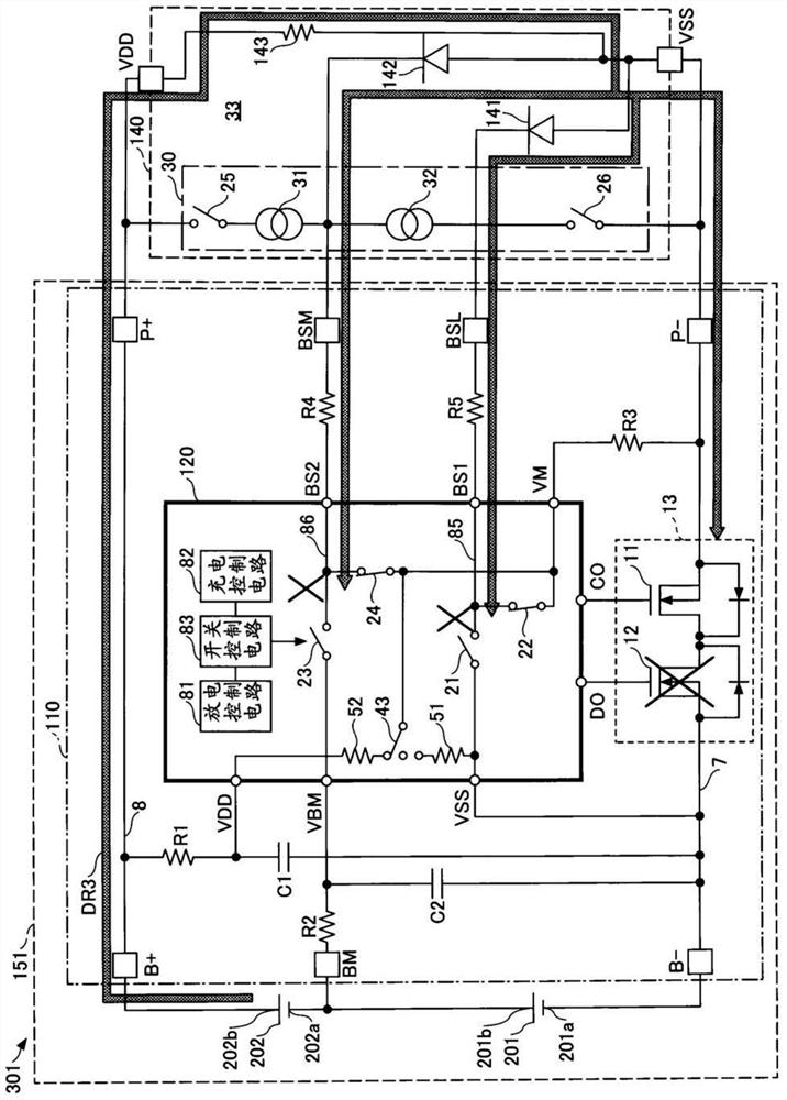
[0141] Figure 9 It is a diagram showing a configuration example of the control system in the third embodiment, and is a diagram showing a discharge path under cell balance control based on discharge of a rechargeable battery cell on the low potential side among a plurality of rechargeable battery cells. Figure 10 It is a diagram showing a configuration example of the control system in the third embodiment, and is a diagram showing a discharge path under cell balance control based on discharge of a rechargeable battery cell on a high potential side among a plurality of rechargeable battery cells. Figure 11 It is a diagram showing an example configuration of the control system in the third embodiment, and is a diagram showing a charging route under cell balance control based on charging of a secondary battery cell on the low potential side among a plurality of secondary battery cells. In the third embodiment, the description of the same configuration as that of the above-ment...
PUM
 Abstract
Description
Claims
Application Information
 - R&D
- Intellectual Property
- Life Sciences
- Materials
- Tech Scout
- Unparalleled Data Quality
- Higher Quality Content
- 60% Fewer Hallucinations
Browse by: Latest US Patents, China's latest patents, Technical Efficacy Thesaurus, Application Domain, Technology Topic, Popular Technical Reports.
© 2025 PatSnap. All rights reserved.Legal|Privacy policy|Modern Slavery Act Transparency Statement|Sitemap|About US| Contact US: help@patsnap.com