
Micropositioner and motion device

A technology of micro-motion table and driving device, which is applied in the direction of generator/motor, piezoelectric effect/electrostrictive or magnetostrictive motor, program-controlled manipulator, etc., which can solve the problem of magnetic interference, heavy load and limited space and other problems to achieve the effect of avoiding magnetic field interference, solving limited space and compact structure

Active Publication Date: 2022-03-01
YINGUAN SEMICON TECH CO LTD
View PDF5 Cites 2 Cited by
  • Summary
  • Abstract
  • Description
  • Claims
  • Application Information

AI Technical Summary

Problems solved by technology

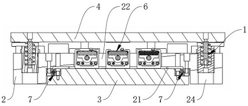
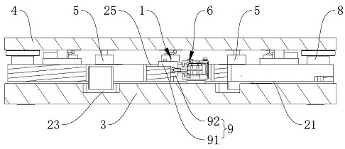
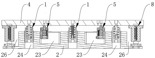
[0004] The purpose of the present invention is to provide a micro-motion stage and motion device with a flat structure, applicable to heavy loads, and driven by piezoelectricity, so as to solve the problems of limited space, heavy load and magnetic interference in some applications in the related art. question

Method used


Image

  • Micropositioner and motion device
  • Micropositioner and motion device
  • Micropositioner and motion device

Examples


Embodiment Construction

[0043] The present invention will be further described in detail below in conjunction with the accompanying drawings and embodiments. It should be understood that the specific embodiments described here are only used to explain the present invention, but not to limit the present invention. In addition, it should be noted that, for the convenience of description, only some structures related to the present invention are shown in the drawings but not all structures.

[0044] In the description of the present invention, unless otherwise clearly specified and limited, the terms "connected", "connected" and "fixed" should be understood in a broad sense, for example, it can be a fixed connection, a detachable connection, or an integrated ; It can be a mechanical connection or an electrical connection; it can be a direct connection or an indirect connection through an intermediary, and it can be the internal communication of two components or the interaction relationship between two ...


PUM


Abstract

The invention discloses a micropositioner and a motion device, and relates to the technical field of precision motion. The micropositioner comprises a middle seat, a fixed base, a bearing table, a horizontal driving device, a vertical driving device and a gravity compensation device, and a containing groove is formed in the bottom of the middle seat; the fixed base is located in the containing groove, and avoiding holes are formed in the groove bottom of the containing groove and / or the fixed base. The bearing table is mounted above the middle seat; the horizontal driving device is a piezoelectric driving device and is arranged in the avoiding hole; the vertical driving device is a piezoelectric driving device and is located on the circumferential outer side of the containing groove, and the lower end of the vertical driving device extends into and is installed in the middle base. The lower end of the gravity compensation device extends into the middle base and is located on the circumferential outer side of the containing groove, and the upper end of the gravity compensation device extends out of the upper end face of the middle base and is connected with the bearing table. The loading problem is effectively solved through the gravity compensation device, the height of the whole device is reduced through the flat design, and the structure is more compact.

Description

technical field [0001] The invention relates to the technical field of precision motion, in particular to a micro-motion table and a motion device. Background technique [0002] With the development of science and technology, in the field of precision motion, the piezoelectric motor represented by the inverse piezoelectric effect is gradually taking the core position of the actuator together with the electromagnetic motor due to its unique advantages. [0003] In the field of precision displacement, piezoelectric drive technology has the characteristics of no magnetic interference, and under the same driving force, piezoelectric motors are significantly smaller than electromagnetic motors, and require less space. However, some applications (such as micro-motion table) have very strict requirements on space, but the load is relatively heavy. Although the piezoelectric motor with large load can drive heavy loads, it cannot be applied to motion devices due to space constraints....

Claims


Application Information

Patent Timeline
IPC IPC(8): H02N2/02H02N2/04B25J9/00
CPCH02N2/028H02N2/043B25J9/0096
Inventor 郝凌凌王振华
Owner YINGUAN SEMICON TECH CO LTD
Features
  • Generate Ideas
  • Intellectual Property
  • Life Sciences
  • Materials
  • Tech Scout
  • Unparalleled Data Quality
  • Higher Quality Content
  • 60% Fewer Hallucinations
Learn More