Self-walking equipment system

A self-propelled and equipment technology, applied in control/adjustment systems, non-electric variable control, instruments, etc., can solve the problems of high cost of magnetic strips, limited use range, inability to effectively identify the working range, etc., to achieve low cost, easy The effect of detection

Inactive Publication Date: 2016-02-17
NINGBO DELIN MACHINERY
View PDF7 Cites 5 Cited by
  • Summary
  • Abstract
  • Description
  • Claims
  • Application Information

AI Technical Summary

Problems solved by technology

[0002] Self-propelled devices such as sweeping robots and lawn-mowing robots are very common in daily life. When each self-propelled device is working, it is necessary to delineate the working range for the self-propelled device. There are many ways to set the working range of the self-propelled device on the market, such as Infrared, video recognition, magnetic strips, etc., these methods have some shortcomings in application: infrared is susceptible to sunlight interference, and is not suitable for long-term outdoor use, video recognition is not suitable for long-term outdoor use, and the cost of magnetic strips is high. The range is limited and it is not easy to promote. For the above-mentioned methods, they all have one thing in common, that is, they cannot effectively identify the inside and outside of the working range, and cannot reliably ensure that the self-propelled equipment works normally when it is within its ow

Method used


Image

  • Self-walking equipment system
  • Self-walking equipment system
  • Self-walking equipment system

Examples


Embodiment Construction

[0018] Reference Figure 1~4 The present invention will be further explained.

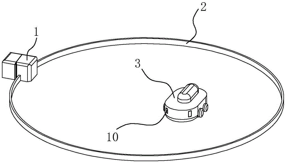
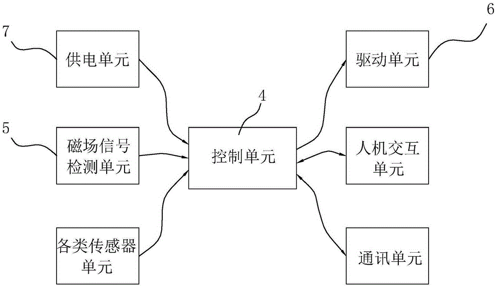
[0019] Such as figure 1 with figure 2 As shown, a self-propelled device 3 system includes a signal generating device 1, a wire 2 for setting the working area of ​​the self-propelled device 3, and a self-propelled device 3. The wire 2 and the signal generating device 1 form a closed-loop conductive circuit and are connected The two sides of the wire 2 generate magnetic fields in opposite directions. The self-propelled device 3 includes a drive unit 6, a control unit 4, and at least one magnetic field signal detection unit 5 arranged on its body. The magnetic field signal detection unit 5 is based on the magnitude and A detection signal is output in the direction. The control unit 4 receives the detection signal and controls the self-propelled equipment 3 to move in the working area according to the detection signal. The signal generating device 1 includes a pseudo-random pulse signal generator, which ...


PUM


Abstract

The invention discloses a self-walking equipment system. The self-walking equipment system comprises a signal generating device, a wire for setting the work region of self-walking equipment, and the self-walking equipment. A closed-loop conducting loop is formed by the wire and the signal generating device. The self-walking equipment comprises a driving unit, a control unit and at least one magnetic field signal detecting unit, all of which are arranged on a body of the self-walking equipment. The magnetic field detecting units output detection signals according to the sizes and directions of detected magnetic fields, and the control unit receives the detection signals and controls the self-walking equipment to move in the work region according to the detection signals. The signal generating device comprises a pseudo-random pulse signal generator adapting to the length of the wire and outputting signal pulses, and a constant current unit. Compared with the prior art, the constant current unit is additionally arranged, and therefore the magnitude of signal current in the wire is stabilized; the pseudo-random pulse signal generator is additionally arranged, and therefore magnetic field signals inside and outside the wire are easier to detect, and the self-walking equipment system is low in cost, simple and practical.

Description

Technical field [0001] The invention relates to the field of automatic control, and more specifically, it relates to a self-propelled equipment system. Background technique [0002] Self-propelled equipment such as sweeping robots and lawn mower robots are very common in life. When each self-propelled equipment is working, it is necessary to delimit the working range of the self-propelled equipment. At present, there are many ways to set the working range of self-propelled equipment on the market, such as Infrared, video recognition, magnetic strips, etc., these methods have some shortcomings in their applications: infrared is easily interfered by sunlight and is not suitable for long-term outdoor use, and video recognition is not suitable for long-term outdoor use. Magnetic strips are costly and use The scope is limited and it is not easy to promote. For each of the above methods, they all have one thing in common, that is, they cannot effectively identify the inside and outside...

Claims


Application Information

Patent Timeline
IPC IPC(8): G05D1/02
CPCG05D2201/0208G05D1/0265
Inventor 陈建平王双马顺杰陆立孟
Owner NINGBO DELIN MACHINERY
Why Eureka
Try Eureka