Direct-current transmission line distance measurement method and system

A technology of DC transmission line and ranging method, which is applied in the direction of the fault location, etc., can solve the problems of unreliable fault ranging, long fault ranging time, and inability to measure the full length of the line, etc., and achieves strong anti-noise ability and low ranging cost Low, strong anti-transition resistance effect

Pending Publication Date: 2022-03-04
KUNMING UNIV OF SCI & TECH
View PDF9 Cites 2 Cited by
  • Summary
  • Abstract
  • Description
  • Claims
  • Application Information

AI Technical Summary

Problems solved by technology

[0004] The technical problem to be solved by the present invention is to provide a method and system for distance measurement of direct current transmission lines, using single-ended data for fault distance measurement, which can realize accurate measurement of fault distances, and aims to solve the problem of fault detection in the case of high-impedance faults in existing direct current transmission lines. The problems of unreliable distance, long fault location time and inability to measure the full length of the line

Method used


Image

  • Direct-current transmission line distance measurement method and system
  • Direct-current transmission line distance measurement method and system
  • Direct-current transmission line distance measurement method and system

Examples


Embodiment 1

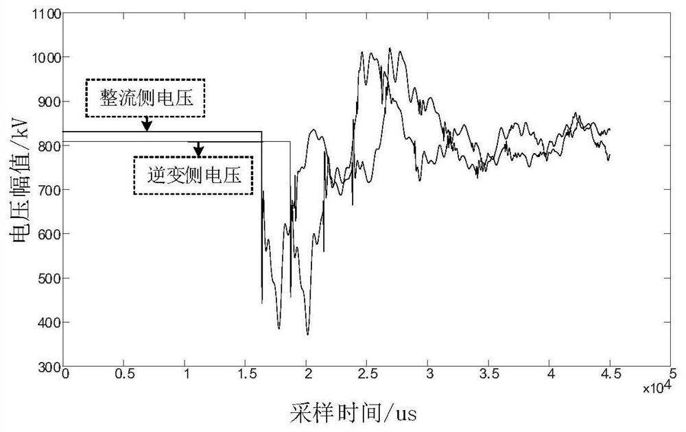
[0055] Embodiment 1: First, build a direct current transmission line model in PSCAD / EMTDC, the line length is 1500km, the voltage level is ±800kV, and the sampling frequency is 1MHz. A high-resistance phase-to-phase short-circuit fault occurs at a distance of 400km.

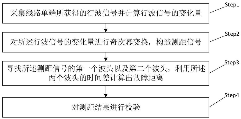
[0056] Such as figure 1 As shown, a DC transmission line ranging method, including

[0057] Step1: Collect the voltage signal obtained by the single-end of the line and calculate the variation of the voltage signal.

[0058] Step2: Perform an odd power transformation on the variation of the voltage signal to construct a ranging signal.

[0059] Step3: Find the first wave head and the second wave head of the ranging signal, and use the time difference between the two wave heads to calculate the fault distance.

[0060] Ste,4: Verify the ranging result.

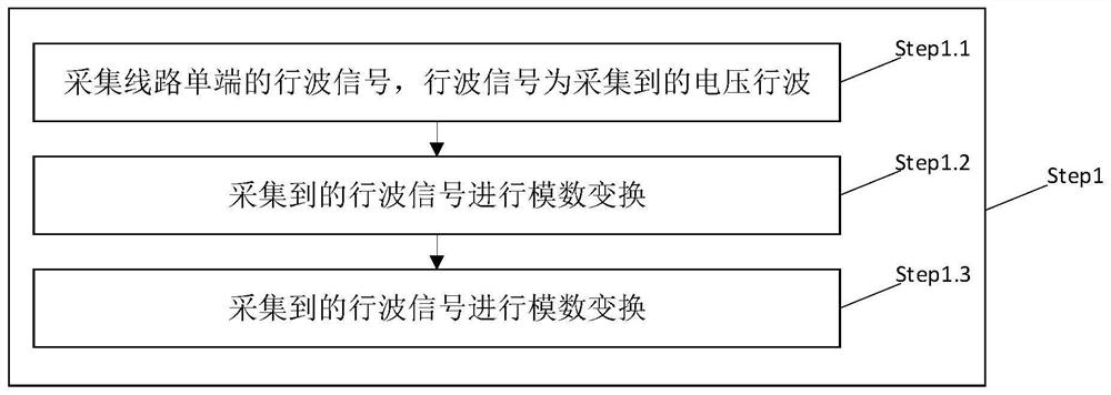
[0061] Such as figure 2 As shown, Step1 specifically includes:

[0062] Step1.1: Collect the single-ended voltage signal of the line, and the voltage signa...

Embodiment 2

[0085] Example 2, such as Figure 8 As shown, a DC transmission line ranging system includes:

[0086] The data collection module 101 is used to collect the voltage signal obtained from the single end of the line.

[0087] The numerical calculation module 201 is used to calculate the variation of the voltage signal, calculate the odd power of the voltage transformation, calculate the fault distance, and calculate the absolute value of the first wave head slope.

[0088] The logic judgment module 301 is used for judging the magnitude of the absolute value of the first wave head slope between the measuring end and the opposite end.

[0089] Wherein, the described distance measuring method and system of a direct current transmission line is characterized in that the data acquisition module specifically includes:

[0090] The data collection unit 1011 is used to collect the voltage signal of the DC transmission line in real time from the measured units such as sensors and other ...


PUM


Abstract

The invention relates to a direct-current power transmission line distance measurement method and system, and belongs to the technical field of power system relay protection. The method comprises the following steps: acquiring a voltage signal obtained by a single end of a line and calculating the variable quantity of the voltage signal; odd power transformation is carried out on the variable quantity of the voltage signal, and a ranging signal is constructed; and searching a first wave head and a second wave head of the distance measurement signal, calculating a fault distance by using a time difference between the two wave heads, and verifying a distance measurement result. The invention further provides a direct-current transmission line distance measuring system. According to the method, only single-ended quantity is utilized, synchronous time synchronization is not needed, the anti-noise capability is high, and distance measurement can be accurately carried out.

Description

technical field [0001] The invention relates to a distance measuring method and system for a direct current transmission line, belonging to the technical field of relay protection of electric power systems. Background technique [0002] my country's energy and loads are unevenly distributed from east to west, and most clean energy such as wind power and photovoltaic power generation in the northwest and hydropower in the southwest are transmitted to the load center in the east. High-voltage direct current transmission has unique advantages such as large transmission capacity and long transmission distance; simple structure of transmission poles and towers, narrow transmission corridors, few transmission lines, and low transmission loss. application. In the process of high-voltage direct current transmission, overhead lines are mainly used, the distance of direct current transmission is long, and the transmission lines are distributed in different terrains and environmental ...

Claims


Application Information

Patent Timeline
Patent Type & Authority Applications(China)
IPC IPC(8): G01R31/08
CPCG01R31/08
Inventor 束洪春李文龙唐玉涛杨竞及王锐马海心薄志谦
Owner KUNMING UNIV OF SCI & TECH
Why Eureka
Try Eureka