High-voltage insulator detection device
A technology of high-voltage insulators and detection devices, which is applied in the direction of testing dielectric strength, etc., and can solve problems such as the inability to ensure close contact between high-voltage contacts and insulators
- Summary
- Abstract
- Description
- Claims
- Application Information
AI Technical Summary
Problems solved by technology
Method used
Image

Examples
Embodiment 1
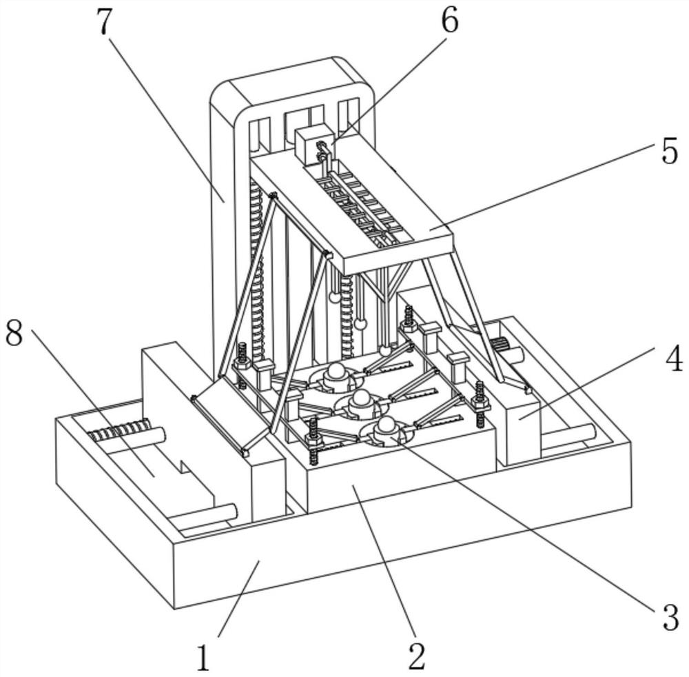
[0028] Embodiment one, by Figure 1-Figure 5 Given, the present invention includes a base 1 and an insulator body 3, the number of the insulator bodies 3 is three, and the three insulator bodies 3 are all located above the base 1, grooves 8 are opened on both sides of the top of the base 1, and the grooves 8 is equipped with a sufficient extrusion mechanism 4, the top of the base 1 is fixedly installed with an insulator limit mechanism 2, the insulator body 3 is connected with the insulator limit mechanism 2, and the top of the base 1 is fixedly installed with a side plate 7 near the rear side. The front of plate 7 is equipped with top board 5 movablely, and the top of top board 5 is equipped with power supply mechanism 6, and full extruding mechanism 4 is connected with top board 5.
Embodiment 2
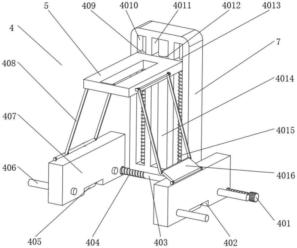
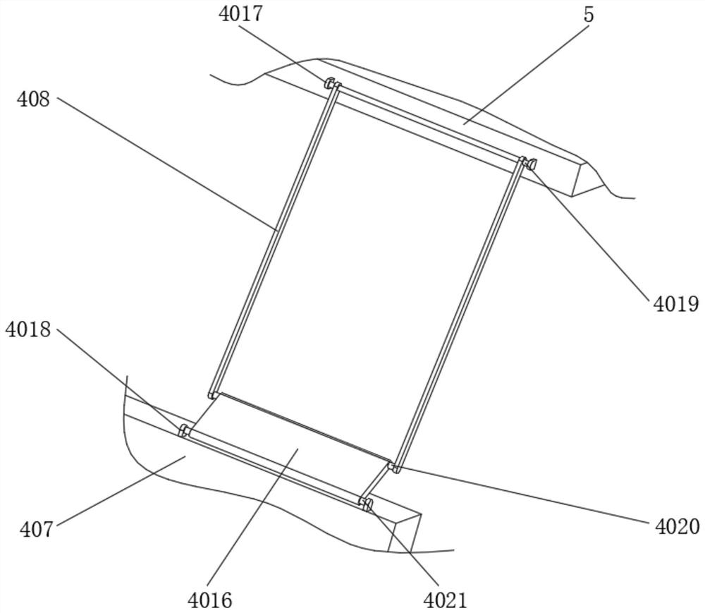
[0029]Embodiment 2, on the basis of Embodiment 1, the sufficient extrusion mechanism 4 includes a motor 401 located inside the groove 8, the left end of the motor 401 is fixedly connected with a transmission shaft 403, and the outside of the transmission shaft 403 is provided with two external threads 404 , the arrangement of the two external threads 404 is opposite, and the transmission shaft 403 is respectively threaded with two slide plates 407 through the two external threads 404, and the two slide plates 407 are both located inside the groove 8 and are movably engaged with the groove 8 , and the bottom end of the slide plate 407 does not fit the bottom of the inner cavity of the groove 8, and both sides of the groove 8 are fixedly connected with cross bars 406, and the cross bar 406 is movably socketed with the slide plate 407, and the bottoms of the two slide plates 407 Bottom groove 402 is provided in the middle, and the inside of bottom groove 402 is fixedly connected w...
Embodiment 3
[0031] Embodiment 3, on the basis of Embodiment 1, the power supply mechanism 6 includes a test power supply 601 that is located at the top of the top plate 5 and is fixedly connected to the top plate 5. Both sides of the front side of the test power supply 601 are fixedly equipped with terminal blocks 602. A wire 609 is fixedly connected between the heads 602, a through groove 604 is opened in the middle of the top plate 5, the wire 609 is located inside the through groove 604, and a protective sleeve 608 is fixedly sleeved on the outside of the wire 609, and both sides of the protective sleeve 608 are fixed at equal distances. A fixed rod 603 is installed, and the fixed rod 603 is fixedly connected with the inner wall of the through groove 604. The outer side of the wire 609 is fixedly sleeved with two support sleeves 6010, and the two support sleeves 6010 are located below the protective sleeve 608. The conductive rod 606 is fixedly installed at a distance, and the bottom en...
PUM
 Abstract
Description
Claims
Application Information