Supercharge Your Innovation With Domain-Expert AI Agents!

LED lamp control system

A technology of LED lights and control systems, applied in the direction of electrical components, etc., can solve the problems of high cost pressure, achieve the effects of reducing costs, realizing dimming functions, and good application value

Pending Publication Date: 2022-03-04
上海福太隆汽车电子科技有限公司
View PDF0 Cites 0 Cited by
  • Summary
  • Abstract
  • Description
  • Claims
  • Application Information

AI Technical Summary

Problems solved by technology

[0005] The purpose of the present invention is to overcome the problem of high cost pressure of the existing LED control system and provide a LED lamp control system

Method used


Image

  • LED lamp control system
  • LED lamp control system

Examples


Embodiment Construction

[0029] The following will clearly and completely describe the technical solutions in the embodiments of the present invention with reference to the accompanying drawings in the embodiments of the present invention. Obviously, the described embodiments are only some, not all, embodiments of the present invention. Based on the embodiments of the present invention, all other embodiments obtained by persons of ordinary skill in the art without making creative efforts belong to the protection scope of the present invention.

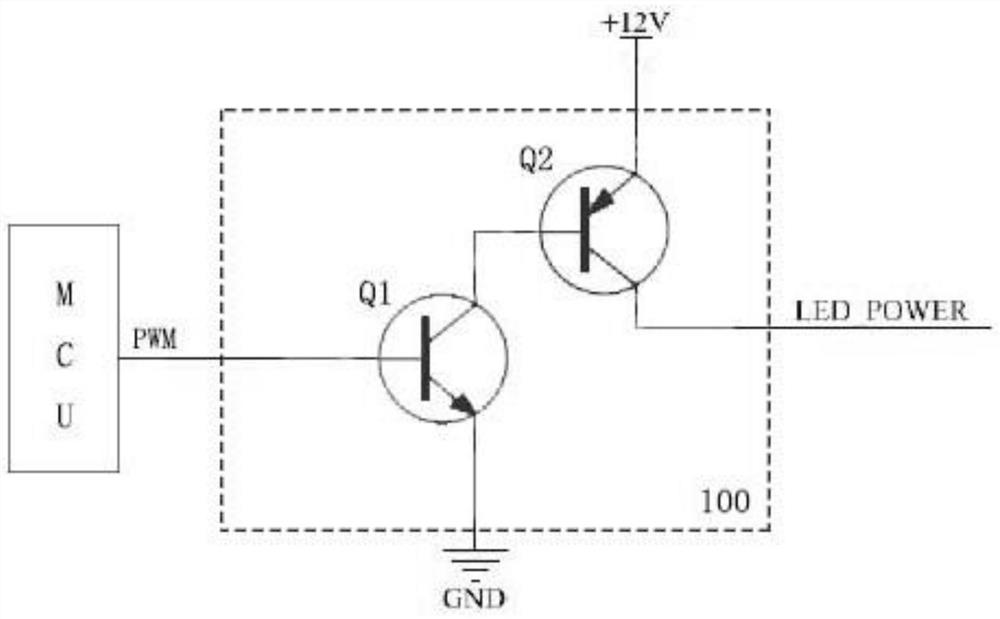
[0030] see figure 1 , this embodiment provides a technical solution: an LED lamp control system, including: MCU chip, multiple LED lamps, a brightness control unit and multiple sub-switch control units;

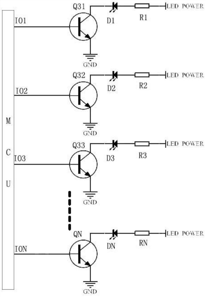
[0031] The MCU chip includes a PWM interface and a plurality of IO interfaces, the PWM interface is connected to the brightness control unit, the brightness control unit is connected to a plurality of LED lamps, each of the IO interfaces is connected to one o...


PUM


Abstract

The invention relates to the technical field of circuit control, and discloses an LED lamp control system, which comprises an MCU chip, a plurality of LED lamps, a brightness control unit and a plurality of sub-switch control units, the brightness control unit comprises a first triode and a second triode; the sub-switch control unit comprises a third triode; a PWM interface of the MCU chip outputs a brightness adjusting signal, the brightness adjusting signal controls the first triode and the second triode to adjust a voltage signal input by the voltage input end and then outputs a brightness control signal, and the brightness control signal is used for controlling the brightness of a plurality of LED lamps; when the IO interface of the MCU chip outputs a current signal, the current signal is amplified by the third triode corresponding to the sub-switch control signal, and then the corresponding LED lamp is lightened, the dimming function can be realized, the indicating lamp to be lightened can be lightened according to the actual requirement, the cost is reduced, and the circuit has good application value in the fields of industry, airplanes, steamships and the like.

Description

technical field [0001] The invention relates to the technical field of circuit control, in particular to an LED lamp control system. Background technique [0002] In the process of electronic product design, more and more products use indicator lights to display product functions, and the brightness of indicator lights in different external environments is also different. For example, the indicator light has one brightness level during the day, and another indicator light at night. In this case, the indicator light needs to be dimmed. [0003] At present, it is common in the market to use the integrated processing chip, that is, the PWM interface of the MCU chip to directly dim the indicator lights. One PWM interface controls one LED light. There are several LED lights on the product, and several PWM interfaces are required correspondingly. However, the PWM interface of the MCU chip is limited. For example, the PIC18F series of Microchip has only 4 PWM interfaces. In a prod...

Claims


Application Information

Patent Timeline
Patent Type & Authority Applications(China)
IPC IPC(8): H05B45/10H05B45/325
CPCH05B45/10H05B45/325
Inventor 周纬璐
Owner 上海福太隆汽车电子科技有限公司
Features
  • R&D
  • Intellectual Property
  • Life Sciences
  • Materials
  • Tech Scout
  • Unparalleled Data Quality
  • Higher Quality Content
  • 60% Fewer Hallucinations
Learn More