Adjustable front windshield glass mounting and positioning stop block and using method

A windshield, installation and positioning technology, applied to windshields, windows, transportation and packaging, etc., can solve the problems of high logistics costs, failure of block functions, and increased space occupied by windshields, etc., to achieve long-term and effective support , the effect of large adjustment space

Pending Publication Date: 2022-03-08
ANHUI JIANGHUAI AUTOMOBILE GRP CORP LTD
View PDF0 Cites 0 Cited by
  • Summary
  • Abstract
  • Description
  • Claims
  • Application Information

AI Technical Summary

Problems solved by technology

At present, the installation and positioning or limit methods are often used: 1. The windshield glass has its own positioning column, but the positioning column is fixed on the windshield glass, which increases the space occupied by the windshield glass. It uses shelf transfer, and the logistics cost per piece Big
And after the position of the windshield is adjusted in place, the glass glue is not completely cured and can slide. The structure of the positioning column cannot prevent the windshield from sliding under the influence of its own weight; position, but the position of the stopper is affected by the hole position of the body. When the deviation of the hole position of the body is large, the function of the stopper may fail. In addition, the stopper structure cannot provide a holding measure to prevent the windshield from slipping after the windshield is adjusted in place.

Method used


Image

  • Adjustable front windshield glass mounting and positioning stop block and using method
  • Adjustable front windshield glass mounting and positioning stop block and using method
  • Adjustable front windshield glass mounting and positioning stop block and using method

Examples


Embodiment Construction

[0035] Various exemplary embodiments of the present invention will now be described in detail with reference to the accompanying drawings. It should be noted that the relative arrangements of components and steps, numerical expressions and numerical values ​​set forth in these embodiments do not limit the scope of the present invention unless specifically stated otherwise.

[0036] The following description of at least one exemplary embodiment is merely illustrative in nature and in no way taken as limiting the invention, its application or uses.

[0037] Techniques, methods and devices known to those of ordinary skill in the relevant art may not be discussed in detail, but where appropriate, such techniques, methods and devices should be considered part of the description.

[0038] In all examples shown and discussed herein, any specific values ​​should be construed as exemplary only, and not as limitations. Therefore, other instances of the exemplary embodiment may have dif...


PUM


Abstract

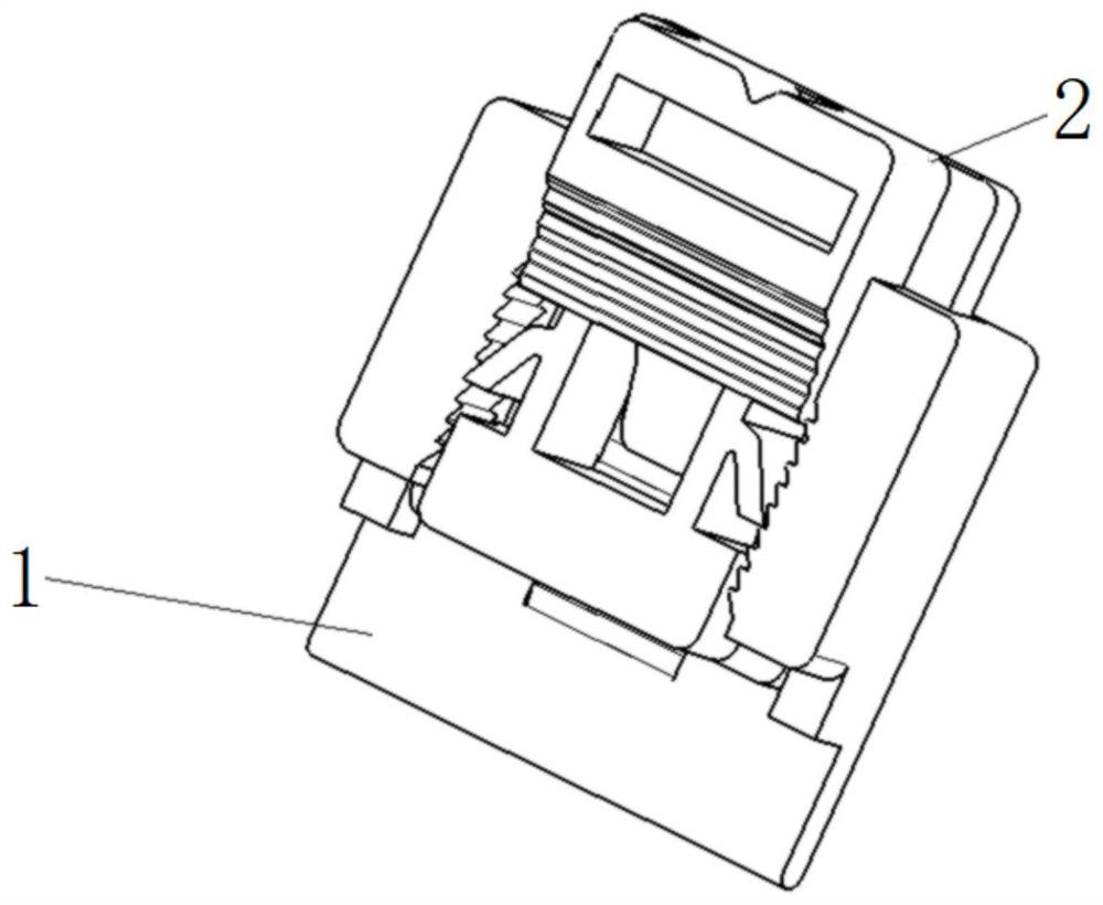
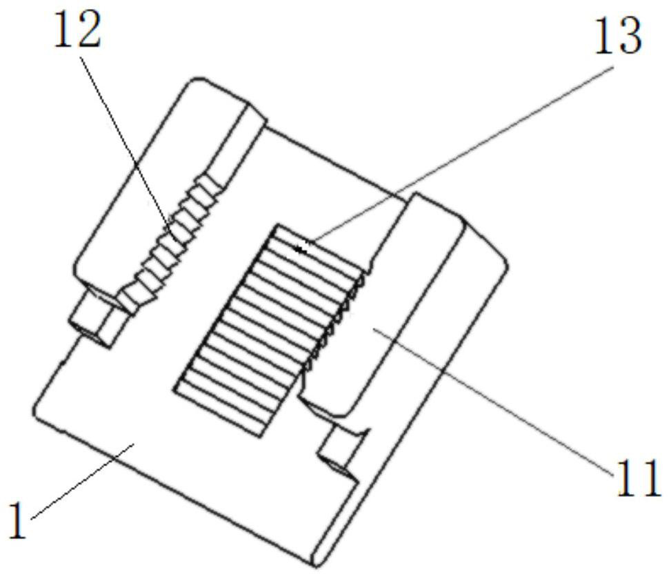
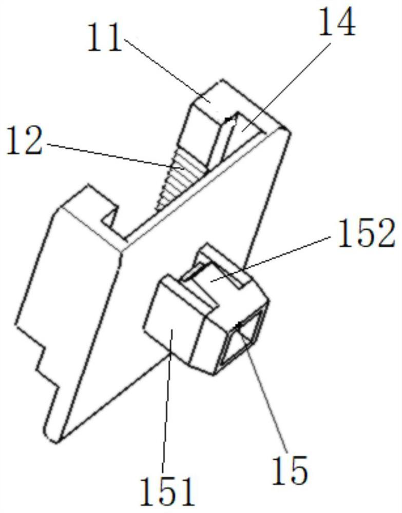
The invention discloses an adjustable front windshield glass mounting and positioning stop block and a use method. The positioning stop block comprises a fixed seat and a movable stop block. A fixing buckle is arranged on the lower end face of the fixing base and used for connecting the fixing base with a vehicle body metal plate. Protruding blocks are arranged on the two sides of the upper end face of the fixing base, sliding grooves are formed in the opposite sides of the protruding blocks in an inwards-concave mode, and the sliding grooves are attached to the fixing base. A first sawtooth face is further arranged on the opposite side of the protruding block. Guide ribs are arranged on the two sides of the movable check block, the guide ribs can slide into the inner sides of the protruding blocks along the sliding grooves, first clamping jaws are further arranged on the two sides of the movable check block and matched with the first sawtooth faces, the side edges, close to the two first clamping jaws, of the movable check block are glass limiting faces, and the glass limiting faces abut against the lower edge of the windscreen to be installed. According to the invention, the influence of vehicle body hole position deviation on windscreen positioning or limiting can be reduced; in addition, the problem of slippage of the windshield glass before the glass cement is completely cured can be avoided.

Description

technical field [0001] The invention relates to the technical field of installation of windshield glass of automobiles, and more particularly relates to an adjustable windshield glass installation positioning stopper and a use method thereof. Background technique [0002] The windshield glass of the car is installed on the front wall frame of the car through glass glue. When installing, the worker should roughly find the installation position of the windshield glass, and then adjust the position of the windshield glass after fastening the windshield glass to make the surroundings match well, and then push the windshield The glass allows the glass glue to fully extend and fully contact the sheet metal surface to ensure a firm paste. Finally, let it stand until the glass glue solidifies. During the entire installation process, workers must rely on positioning or limit structures to determine, adjust and maintain the position of the windshield. At present, the installation an...

Claims


Application Information

Patent Timeline
IPC IPC(8): B60J1/00
CPCB60J1/005B60J1/006
Inventor 林志赵飞吴蕾菲金伟明李佳佳罗世成杨士钦姚学森刘军刘天伍胡杰迟玉华
Owner ANHUI JIANGHUAI AUTOMOBILE GRP CORP LTD
Why Eureka
Try Eureka