Multifunctional high speed clarifier

A clarifier and multi-functional technology, which is applied in the field of sedimentation tank, clarification tank, grit chamber and air flotation tank, can solve the problems of high energy consumption of the clarifier impeller, long time of water retention in the tank, low water treatment rate, etc. Blockage of the aeration head, reduction of air flotation energy consumption, and enhanced separation

Inactive Publication Date: 2005-06-29
高根树
View PDF7 Cites 5 Cited by
  • Summary
  • Abstract
  • Description
  • Claims
  • Application Information

AI Technical Summary

Problems solved by technology

[0007] The mixing reaction time of the clarifier is as long as 10 minutes, the contact flocculation circulation reaches 3~4 times the inlet flow, and the water treatment rate is also very low, so the energy consumption of the impeller of the mechanical agitation clarifier is relatively large
[0008] The aeration head is often blocked in the air flotation sedimentation tank, and the water stays in the tank for too long
Some pools can be as deep as 3m, and need to be equipped with a blower with a wind pressure of more than 30kPa, which consumes too much energy

Method used


Image

  • Multifunctional high speed clarifier
  • Multifunctional high speed clarifier
  • Multifunctional high speed clarifier

Examples


Embodiment Construction

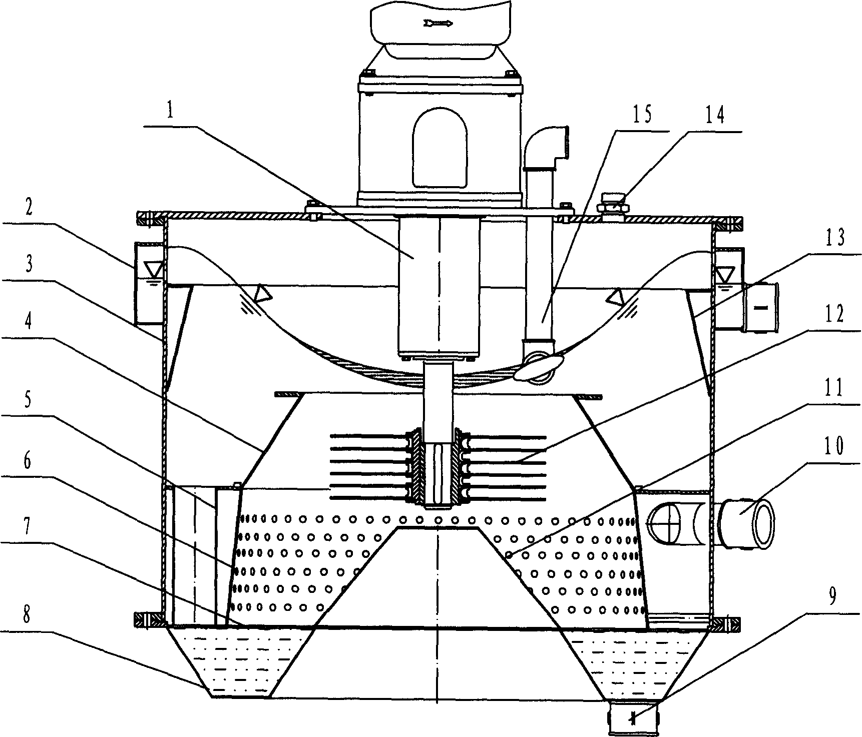
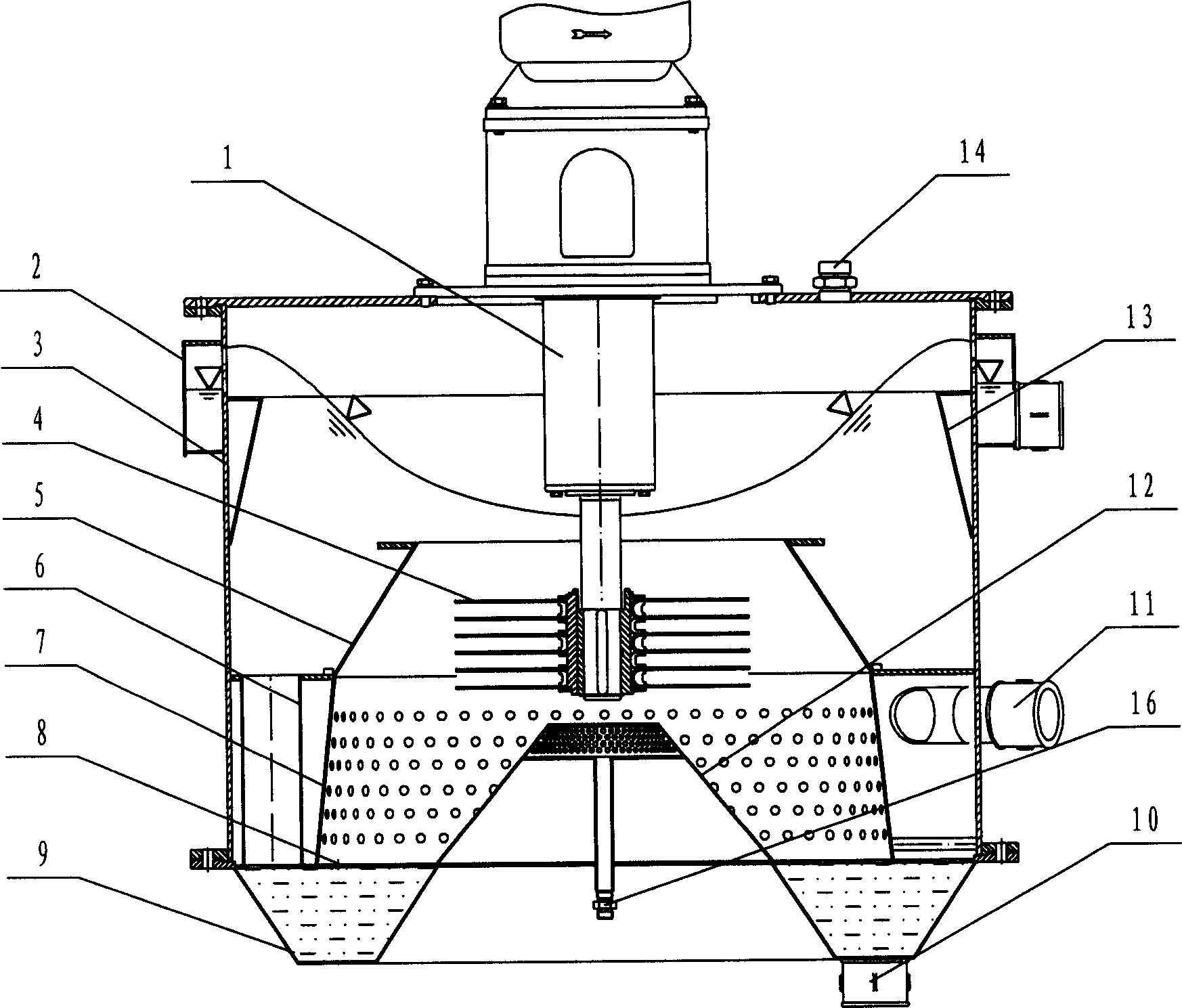
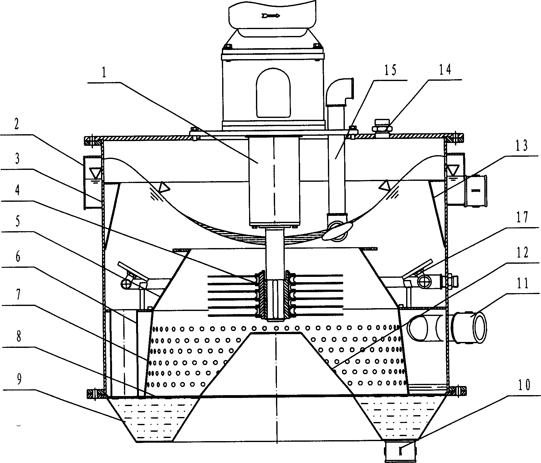
[0076] see figure 1 , which is a skimming precipitator designed according to the technical solution of the present invention. It contains a straight garden cylindrical warehouse 3, a set of transmission device 1, a set of pinwheel 4, thickening mud bucket 9, shielding plate 8, slurry feeding hydrodynamic separator 7, main separation cone 5, tertiary settling cone 13, Skimmer 15.

[0077] Cylindrical bin 3 is a garden tube, with flanges on the upper and lower ends, a slurry inlet pipe 11 connected eccentrically to the bottom, overflow tank 2 connected to the top, and thickening mud bucket 9 is connected with cylindrical bin 3 at the upper part of shielding plate 8. There is a conical frustum 12 in the upper part of the center of the shielding plate 8 . The garden ring separates the slurry inlet area from the hydrodynamic separator 7, and several settling feed pipes 6 are also connected on the garden ring. There are several pile tops between the hydrodynamic separator 7 or th...


PUM

PropertyMeasurementUnit
surface load factoraaaaaaaaaa

Abstract

The invention relates to water processing mechanical technological field, including 3, 1 4,condensing 9, shielding plate 8, 7 main separating 5, tri-13, 15 and 17 . The conventional (1) separates the particle with too large diameter, and too small processing speed of (2) compare with this the invention uses 4 whose line-material is averagely arranged in different layers as the compound (3), depending on water-driving separation, (4) multi-functions to do (5) in the same cavity by steps, increasing the efficiency of separation, enlarging the load 10~100 times, shortening the time for procession, it makes use of (6) to increase the (7), so that equipment size can be smaller and several ones can be compacted into only one, besides, (8) has decreases the air pressure requirement of (9). It can be applied in separation of solid-liquid, fat-water and fiber-water.

Description

1. Technical field [0001] The invention belongs to the technical field of chemical water treatment machinery, and relates to grit chambers, sedimentation ponds, clarification ponds and air flotation ponds. 2. Background technology [0002] Grit chambers, sedimentation tanks, clarification tanks, and air flotation tanks are the basic facilities for industrial wastewater and domestic sewage treatment. [0003] There are many patents on the grit chamber, such as: "Swirl aeration sand removal device (ZL96206538.2)", "Swirl type grit chamber (ZL01110202.0)", "Integrated cyclone sand removal device (ZL01220262 .2)", "A Swirl Grit Settler (ZL02220513.6)", "New Swirl Grit Settler (ZL02264340.0)", "Swirl Grit Settler Impeller (200320120549.1)". These patents have one thing in common, that is, they do not change the bad condition that the grit chamber can only separate particles above 250 microns. [0004] There is no significant progress in the sedimentation tank, and the flat flow...

Claims


Application Information

Patent Timeline
Patent Type & Authority Applications(China)
IPC IPC(8): C02F1/00C02F1/24C02F1/52
Inventor 高根树
Owner 高根树
Why Eureka
Try Eureka