Crimping tool for spliced combined iron core

A technology of combining iron core and tooling, applied in the field of iron core crimping, can solve the problems of iron core damage, crimping tooling is easily damaged, and the crimping tooling cannot locate the iron core, etc., so as to improve the tightness and the pressing efficiency. , to ensure the effect of roundness and coaxiality

Pending Publication Date: 2022-03-11
成都华川电装有限责任公司
View PDF0 Cites 0 Cited by
  • Summary
  • Abstract
  • Description
  • Claims
  • Application Information

AI Technical Summary

Problems solved by technology

[0003] However, for spliced ​​combined iron cores with dovetail grooves and protruding heads, the traditional crimping tooling cannot locate each iron core, and it is very easy to cause damage between the iron cores during the crimping process, and the crimping tooling also cannot It is easy to be damaged, and it is not convenient to return the traditional crimping tooling
Therefore, how to provide a tool that can effectively crimp the spliced ​​combined iron core, form a good positioning of the iron core, and not damage the iron core during the crimping process has not been effectively solved for a long time

Method used


Image

  • Crimping tool for spliced combined iron core
  • Crimping tool for spliced combined iron core
  • Crimping tool for spliced combined iron core

Examples


Embodiment Construction

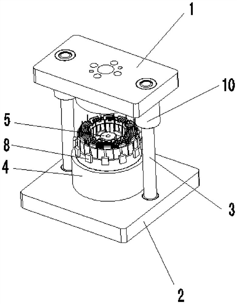
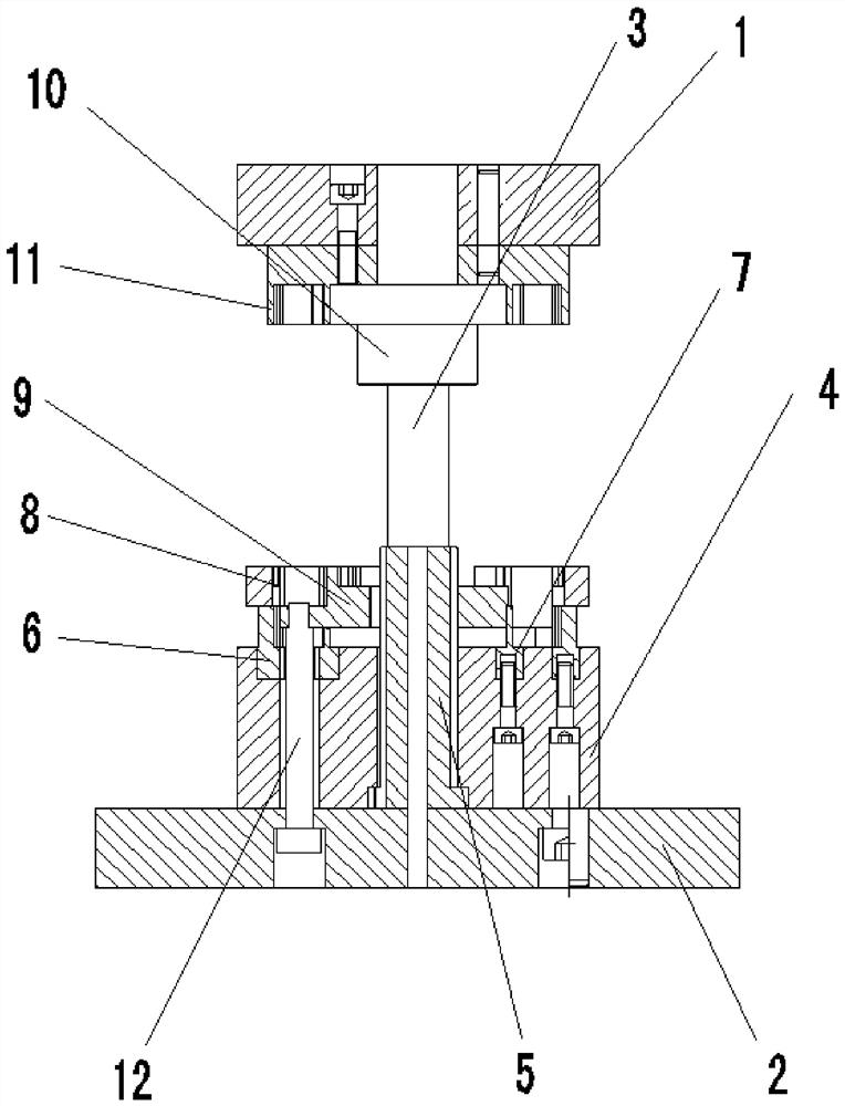
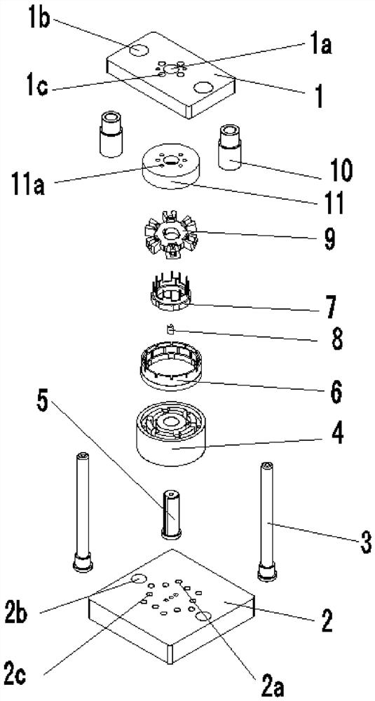
[0023] see Figure 1 to Figure 7 , a crimping tool for splicing combined iron cores, including an upper mounting base 1 and a lower mounting base 2, a plurality of positioning holes 2a are arranged on the lower mounting base 2, and the left and right sides of the upper end surface of the lower mounting base 2 Two guide holes 2b are arranged axisymmetrically, and a guide column 3 is arranged in the guide hole 2b, and a vertical structure is formed between the guide column 3 and the lower mounting seat 2, and a fixed seat 4 is arranged at the center of the upper end of the lower mounting seat 2 , the center of the fixed base 4 is provided with a guide shaft hole 4a, a guide mandrel 5 is arranged in the guide shaft hole 4a, and the height of the guide mandrel 5 is greater than the height of the guide shaft hole 4a. The guide shaft hole 4a of the fixed base 4 is a stepped hole, the upper end of the guide shaft hole 4a is a small-diameter hole, and the lower end is a large-diameter...


PUM


Abstract

The invention relates to a crimping tool for a spliced combined iron core, which comprises an upper mounting seat and a lower mounting seat, a plurality of positioning holes are formed in the lower mounting seat, two guide holes are axially symmetrically formed in the left side and the right side of the upper end surface of the lower mounting seat, guide columns are arranged in the guide holes, and the guide columns and the lower mounting seat are of a vertical structure. A fixed seat is arranged in the center of the upper end of the lower mounting seat, a guide shaft hole is formed in the center of the fixed seat, a guide core shaft is arranged in the guide shaft hole, and the height of the guide core shaft is larger than that of the guide shaft hole; a first groove and a second groove are formed in the fixed seat, a positioning seat is arranged in the first groove, and an index plate is arranged in the second groove; a plurality of positioning grooves are formed in the circumference of the positioning seat, positioning blocks are arranged in the positioning grooves, a material returning block is arranged on the index plate, a shaft hole for a guide core shaft to penetrate through is formed in the center of the material returning block, and a limiting groove for a press-in iron core to be clamped in is formed in an outer extending part of the material returning block.

Description

technical field [0001] The invention relates to the technical field of iron core crimping, in particular to a crimping tool for splicing combined iron cores. Background technique [0002] The traditional iron core is an integral structure, and the iron core is riveted by crimping tooling. After the riveting is completed, the iron core can be taken out of the crimping tooling. [0003] However, for spliced ​​combined iron cores with dovetail grooves and protruding heads, the traditional crimping tooling cannot locate each iron core, and it is very easy to cause damage between the iron cores during the crimping process, and the crimping tooling also cannot It is easy to be damaged, and it is not convenient to return the traditional crimping tooling. Therefore, how to provide a tool that can effectively crimp the spliced ​​combined iron core, form a good positioning of the iron core, and not damage the iron core during the crimping process has not been effectively solved for a...

Claims


Application Information

Patent Timeline
Patent Type & Authority Applications(China)
IPC IPC(8): B23P19/02B23P19/00
CPCB23P19/02B23P19/001B23P19/002
Inventor 刘洋周林邓银意刘慧东
Owner 成都华川电装有限责任公司
Why Eureka
Try Eureka