
Distributed domestic sewage treatment system

A domestic sewage and treatment system technology, applied in the direction of water/sewage treatment, water/sewage treatment equipment, water/sewage multi-stage treatment, etc., to achieve the effect of facilitating installation, disassembly and maintenance, good energy saving and environmental protection, and fast sewage treatment rate

Pending Publication Date: 2022-03-11
浙江友怡环保科技有限公司
View PDF8 Cites 0 Cited by
  • Summary
  • Abstract
  • Description
  • Claims
  • Application Information

AI Technical Summary

Problems solved by technology

[0004] The object of the present invention is to provide a kind of decentralized domestic sewage treatment system, to solve the problems raised in the above-mentioned background technology

Method used


Image

  • Distributed domestic sewage treatment system
  • Distributed domestic sewage treatment system
  • Distributed domestic sewage treatment system

Examples


Embodiment 1

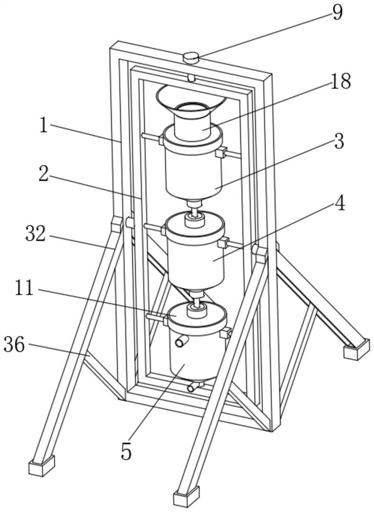
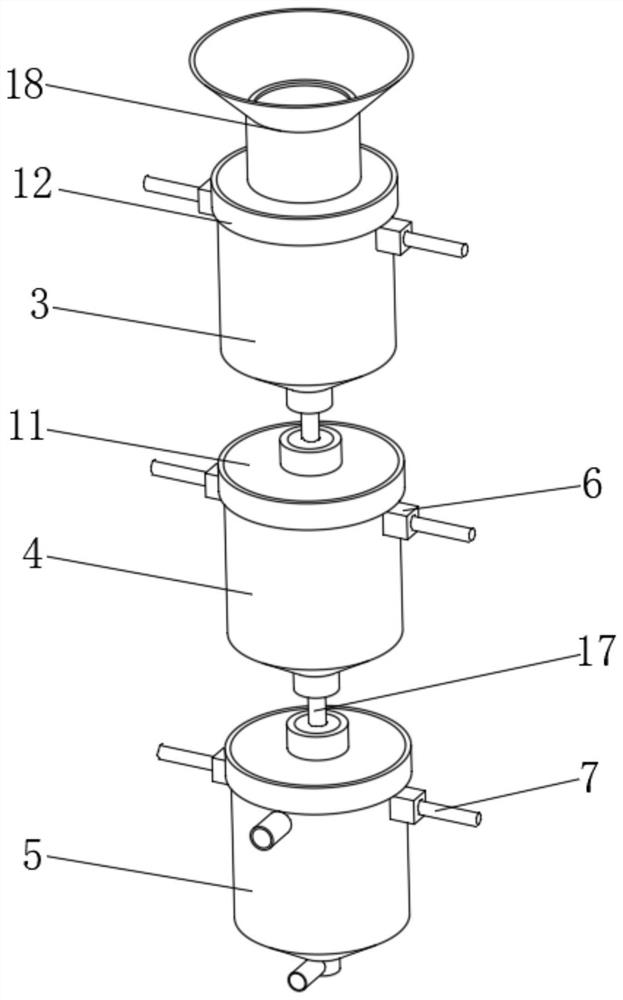
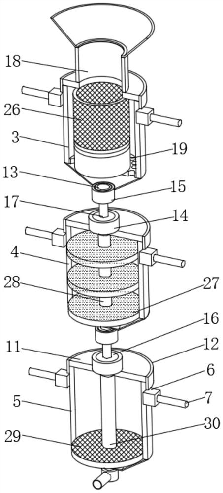
[0030] refer to Figure 1-8 , the present invention provides a technical solution: a decentralized domestic sewage treatment system, including a vertical frame 1, the two sides of the vertical frame 1 are provided with supporting mechanisms close to both sides, and the inside of the vertical frame 1 is provided with a rotating frame 2. Settling tank 3, anaerobic tank 4 and clarification tank 5 are arranged inside the rotating frame 2 from top to bottom. The inside and outside of the rotating frame 2 are equipped with a rotating mechanism. The sedimentation tank 3, anaerobic tank 4 and clarification tank 5 are provided with connecting structures;

[0031] This example refers to Figure 1-4 As shown, the connection structure includes three sets of sealing cover plates 11, the outer surfaces of the three sets of sealing cover plates 11 are fixedly connected with internal thread ring plates 12, and the lower surfaces of the sedimentation tank 3 and the anaerobic tank 4 are fixedl...

Embodiment 2

[0035] This example refers to figure 1 , 5 As shown in -8, the present invention provides a technical solution: a decentralized domestic sewage treatment system, which also includes a rotating mechanism. The rotating mechanism includes two sets of rotating shafts 8 and six sets of fixed shafts 7. Connected to the middle of the two outer walls of the rotating frame 2, six sets of fixed shafts 7 are respectively fixedly connected to the two inner walls of the rotating frame 2, and the outer sides of the sedimentation tank 3, anaerobic tank 4 and clarification tank 5 are all fixedly connected near the top There are two groups of bearing blocks 6, and the bearing blocks 6 are movably connected with the fixed shaft rod 7, the middle position of the upper surface of the vertical frame 1 is provided with a latch 9, and the middle position of the upper side of the rotating frame 2 is provided with a locking hole 10. The vertical frame 1 is clamped with the rotating frame 2 through th...


PUM


Abstract

The invention discloses a distributed domestic sewage treatment system, and relates to the technical field of sewage treatment.The distributed domestic sewage treatment system comprises a vertical frame, supporting mechanisms are arranged on the portions, close to the two sides, of the two side faces of the vertical frame, and a rotating frame is arranged in the vertical frame; a settling barrel, an anaerobic barrel and a clarifying barrel are sequentially arranged in the rotating frame from top to bottom, rotating mechanisms are arranged on the inner side and the outer side of the rotating frame, connecting structures are arranged among the settling barrel, the anaerobic barrel and the clarifying barrel, each rotating mechanism comprises two groups of rotating shafts and six groups of fixed shaft rods, and the two groups of rotating shafts and the six groups of fixed shaft rods are symmetrically arranged. The two rotating shafts are fixedly connected to the middle positions of the two outer side walls of the rotating frame correspondingly. The device has a convenient combination and connection function, is good in leakage-proof sealing performance, facilitates independent disassembly and maintenance of the device, does not need to use a water suction pump, achieves good energy-saving and environment-friendly effects, is high in sewage treatment rate, and facilitates installation, disassembly and maintenance of the device.

Description

technical field [0001] The invention relates to the technical field of sewage treatment, in particular to a distributed domestic sewage treatment system. Background technique [0002] Dispersed domestic sewage is domestic sewage that is scattered over a wide area, diverse in sites, and not easy to be treated in an integrated manner. Commonly found are sewage from various households in rural areas, high-speed service areas, villa areas, and scenic spots. Distributed sewage treatment devices are mostly used. Now Some sewage treatment devices are mostly a single barrel, which is divided into areas inside. Once damaged, the entire barrel needs to be replaced, which is not easy to replace, and the replacement cost is high. [0003] After searching, the Chinese patent No. CN201910914943.8 discloses a distributed domestic sewage treatment device, which reduces the discharge of solid particles, and each barrel can be disassembled by connecting the fixing parts for easy replacement. ...

Claims


Application Information

Patent Timeline
Patent Type & Authority Applications(China)
IPC IPC(8): C02F9/14
CPCC02F9/00C02F1/001C02F2001/007C02F3/28C02F2201/002
Inventor 吴秋明
Owner 浙江友怡环保科技有限公司
Learn More