
Slip frequency type boiler pulse soot blower

A soot blowing device and slip technology, which is applied in the field of boiler soot blowing devices, can solve the problems of large amount of soot blowing at one time, threatening production, and existing space for energy saving, etc.

Pending Publication Date: 2022-03-11
胡建廷
View PDF0 Cites 0 Cited by
  • Summary
  • Abstract
  • Description
  • Claims
  • Application Information

AI Technical Summary

Problems solved by technology

Facts have proved that the steam soot blowing method often damages the boiler tubes, causing tube burst accidents and seriously threatening production. The speed cannot be adjusted dynamically, especially the frequency, which is also the root cause of soot blowing.
Another unfavorable factor is: the cost of steam production is very high, and the amount of soot blowing at one time is also very large, that is, there is room for energy saving

Method used


Image

  • Slip frequency type boiler pulse soot blower
  • Slip frequency type boiler pulse soot blower

Examples


Embodiment Construction

[0007] The present invention is described in further detail below with reference to accompanying drawing:

[0008] Structural description of the present invention is as follows:

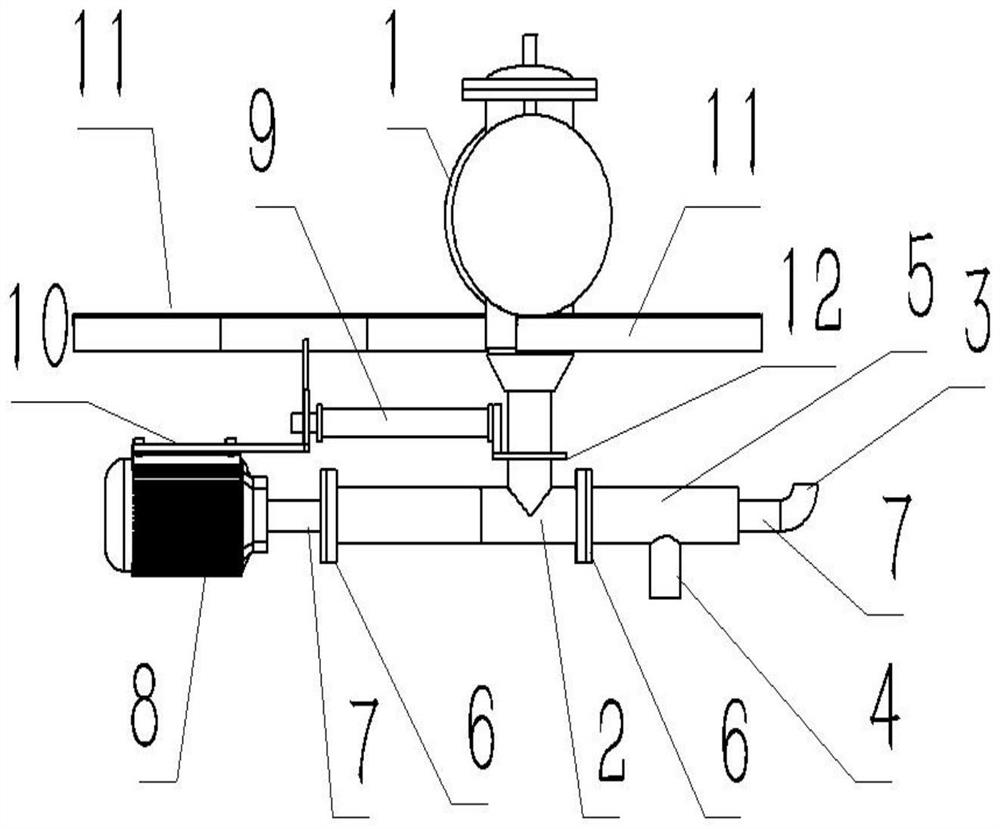
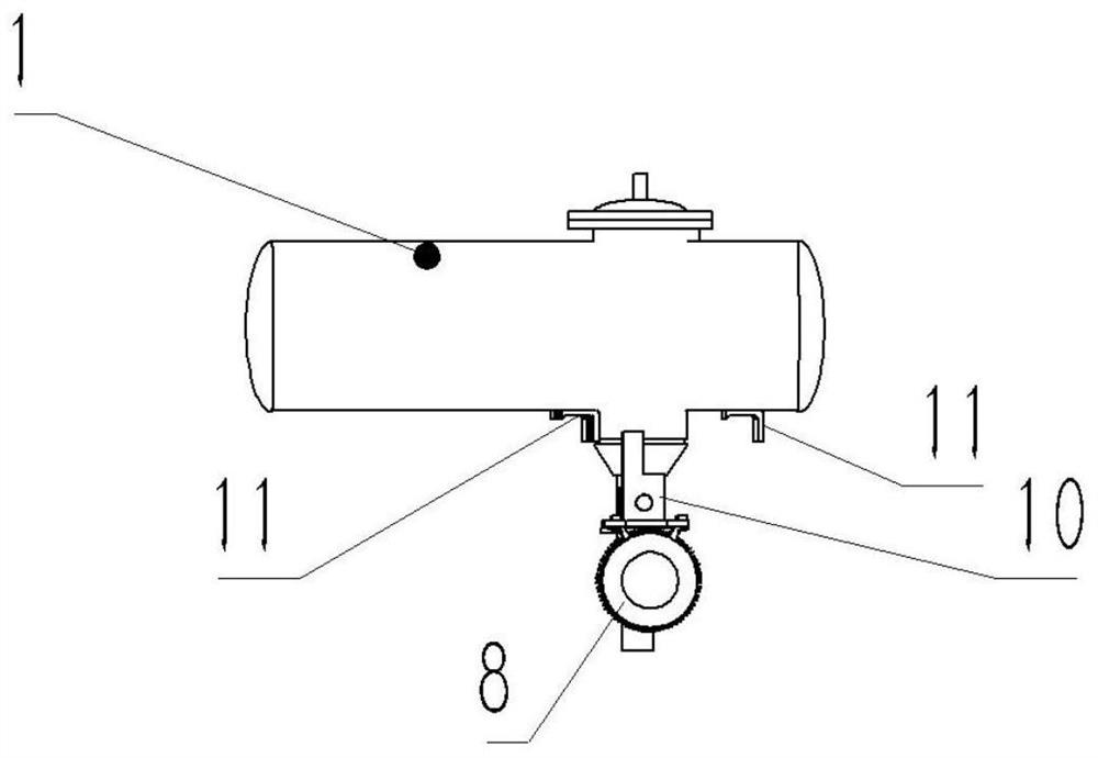
[0009] Refer to attached figure 1 , attached figure 2 As shown, a slip type boiler pulse soot blowing device mainly includes a pulse tank, a telescoping mechanism, a rotating mechanism, a spray explosion tube 7, etc., and a grid hole is provided in the middle of the spray explosion tube 7; the pulse tank Including pulse tank body 1, release valve 13, etc.; the telescopic mechanism includes cylinder 9, bracket two 12, bracket three 10, etc.; The squib 7 is installed in the casing 2 through the butt flange 6; wherein the casing 2 is a three-way pipe, the vertical inlet end of which is connected to the outlet of the release valve 13, and the bracket 2 12 is sleeved in its outer ring, Bracket 2 12 is used to fix the tail end of cylinder 9; the outlet end of described sleeve pipe 2 is connected with f...


PUM


Abstract

The invention relates to a boiler soot blowing device, in particular to a slip frequency type boiler pulse soot blowing device widely used in power station boilers, mainly comprising a pulse tank, a telescoping mechanism, a rotating mechanism, a spray explosion pipe and the like, the pulse tank comprises a pulse tank body, a release valve and the like, the telescoping mechanism is used for pulling the spray explosion pipe close and pull out, and the rotating mechanism is used for rotating the spray explosion pipe. The rotating mechanism is used for achieving axial rotating motion of the spray explosion pipe, and the spray explosion pipe is used for guiding pressure gas in the pressure tank into a dust accumulation area to impact accumulated dust, so that the purpose of blowing dust is achieved.

Description

technical field [0001] The invention relates to a boiler soot blowing device, in particular to a slip type boiler pulse soot blowing device widely used in the electric power production process of boilers of various levels and various types of power stations. Background technique [0002] I graduated from Nanjing Aeronautical Institute in July 1992 with a bachelor’s degree and a major in automatic control. I first served a domestic research institute and have been engaged in power plant boiler combustion optimization and energy-saving and environmental protection technical transformation projects for nearly 30 years. Accumulated a wealth of practical experience, a deep understanding of the working characteristics and advantages and disadvantages of related equipment in the process of burning coal, fuel oil and other fuels in the power production process, coupled with my assiduous research, careful research and development, and developed a number of technically optimized produc...

Claims


Application Information

Patent Timeline
IPC IPC(8): F23J3/02
CPCF23J3/02F23J2700/001
Inventor 胡建廷
Owner 胡建廷
Learn More