Supercharge Your Innovation With Domain-Expert AI Agents!

Optical lens, camera module and electronic equipment

An optical lens and lens technology, applied in optics, optical components, instruments, etc., can solve the problems that it is difficult to adapt to the design requirements of miniaturized electronic equipment, the camera module cannot be miniaturized, and the size of the front end of the lens is difficult to compress. Achieve the effect of realizing miniaturized design, reducing thickness and compressing space

Active Publication Date: 2022-03-11
JIANGXI JINGCHAO OPTICAL CO LTD
View PDF5 Cites 0 Cited by
  • Summary
  • Abstract
  • Description
  • Claims
  • Application Information

AI Technical Summary

Problems solved by technology

At present, most of the high-pixel camera modules on the market often have a limited field of view and do not have a sufficient shooting range.
And if you want a large viewing angle, since the large viewing angle requires the camera module to have a long overall length and a large volume, it is difficult to compress the size of the front end of the lens, which makes the camera module unable to achieve a miniaturized design and is difficult to adapt to miniaturized electronic devices. design requirements

Method used


Image

  • Optical lens, camera module and electronic equipment
  • Optical lens, camera module and electronic equipment
  • Optical lens, camera module and electronic equipment

Examples


no. 1 example

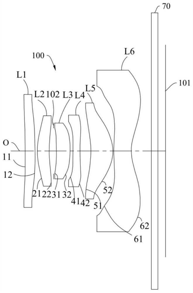
[0104] The structural diagram of the optical lens 100 disclosed in the first embodiment of the present application is as follows figure 1 As shown, the optical lens 100 includes a first lens L1, a second lens L2, a diaphragm 102, a third lens L3, a fourth lens L4, a fifth lens L5, a first lens L1, and a second lens L1 arranged in sequence from the object side to the image side along the optical axis O. Six lens L6, infrared filter 70. Among them, the first lens L1 has a positive refractive power, the second lens L2 has a positive refractive power, the third lens L3 has a positive refractive power, the fourth lens L4 has a negative refractive power, the fifth lens L5 has a positive refractive power, and the sixth lens L3 has a positive refractive power. Lens L6 may have negative optical power.

[0105] Further, the object side 11 of the first lens L1 is concave at the near optical axis O, the image side 12 of the first lens L1 is convex at the near optical axis O; the object s...

no. 2 example

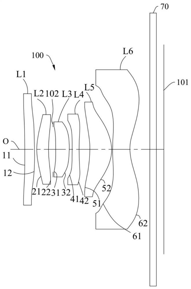
[0120] The structural diagram of the optical lens 100 disclosed in the second embodiment of the present application is as follows image 3 As shown, the optical lens 100 includes a first lens L1, a second lens L2, a diaphragm 102, a third lens L3, a fourth lens L4, a fifth lens L5, a first lens L1, and a second lens L1 arranged in sequence from the object side to the image side along the optical axis O. Six lens L6, infrared filter 70.

[0121] In the second embodiment, the refractive powers of the first lens L1 to the sixth lens L6 are the same as those of the first embodiment.

[0122] In the second embodiment, the surface design of each object side and image side of the first lens L1 to the sixth lens L6 at the near optical axis and the surface design at the circumference are the same as the first lens of the first embodiment. L1 to the sixth lens L6 are the same and will not be repeated here.

[0123] Specifically, taking the effective focal length f=2.671mm of the optic...

no. 3 example

[0131] The structural diagram of the optical lens 100 disclosed in the third embodiment of the present application is as follows Figure 5 As shown, the optical lens 100 includes a first lens L1, a second lens L2, a diaphragm 102, a third lens L3, a fourth lens L4, a fifth lens L5, a first lens L1, and a second lens L1 arranged in sequence from the object side to the image side along the optical axis O. Six lens L6, infrared filter 70.

[0132]In the third embodiment, the refractive power of the first lens L1 to the sixth lens L6 is the same as that of the first embodiment, and the surfaces of the object side and the image side of the first lens L1 to the sixth lens L6 at the near optical axis Type design is the same as the first embodiment.

[0133] In the third embodiment, different from the first embodiment, the object side 11 of the first lens L1 is concave at the circumference, and the image side 12 is convex at the circumference. The surface designs of the object side,...


PUM


Abstract

An optical lens, a camera module and an electronic device, the optical lens comprises a first lens, a second lens, a third lens, a fourth lens, a fifth lens and a sixth lens which are sequentially arranged along an optical axis from an object side to an image side, the first lens has focal power, the object side surface and the image side surface of the first lens are concave and convex near the optical axis, the second lens has positive focal power, and the sixth lens has negative focal power. The third lens has positive focal power, and the object side surface and the image side surface of the third lens are concave surfaces and convex surfaces near the optical axis; the fourth lens has negative focal power, and the object side surface and the image side surface of the fourth lens are convex and concave near the optical axis; the fifth lens has positive focal power, and the object side surface and the image side surface of the fifth lens are concave and convex near the optical axis; the sixth lens has negative focal power, and the object-side surface and the image-side surface of the sixth lens are convex and concave near the optical axis. According to the optical lens, the camera module and the electronic equipment, a large-viewing-angle shooting effect can be realized on the basis of considering the miniaturization design requirement.

Description

technical field [0001] The invention relates to the technical field of optical imaging, in particular to an optical lens, a camera module and electronic equipment. Background technique [0002] With the gradual popularization and upgrading of electronic devices (such as mobile phones, tablet computers, smart watches, etc.), the requirements for imaging quality and miniaturization design of camera modules are also getting higher and higher. At present, most of the high-pixel camera modules on the market often have a limited field of view and do not have a sufficient shooting range. And if you want a large viewing angle, since the large viewing angle requires the camera module to have a long overall length and a large volume, it is difficult to compress the size of the front end of the lens, which makes the camera module unable to achieve a miniaturized design and is difficult to adapt to miniaturized electronic devices. design requirements. Contents of the invention [00...

Claims


Application Information

Patent Timeline
Patent Type & Authority Applications(China)
IPC IPC(8): G02B13/00G02B13/06G02B13/18G03B17/12G03B30/00
CPCG02B13/0045G02B13/06G02B13/18G03B17/12G03B30/00
Inventor 谢晗李明
Owner JIANGXI JINGCHAO OPTICAL CO LTD
Features
  • R&D
  • Intellectual Property
  • Life Sciences
  • Materials
  • Tech Scout
  • Unparalleled Data Quality
  • Higher Quality Content
  • 60% Fewer Hallucinations
Learn More