Supercharge Your Innovation With Domain-Expert AI Agents!

Transformer with high coupling efficiency

A technology for transformers and high-voltage wires, applied in the field of transformers, can solve the problems of large spacers, poor coupling efficiency, and the length of the bobbin body 12 cannot be shortened, and achieve high coupling efficiency

Inactive Publication Date: 2004-08-25
DARFON ELECTRONICS CORP
View PDF0 Cites 0 Cited by
  • Summary
  • Abstract
  • Description
  • Claims
  • Application Information

AI Technical Summary

Problems solved by technology

[0004] However, since the low-voltage wires 13 and the high-voltage wires 14 are wound on the same bobbin body 12 to form a linear arrangement, the low-voltage winding loops on the coil winding areas 18, 24 on both sides of the bobbin body 12 and the high-voltage winding The loop coupling efficiency is poor, and the length of the bobbin body 12 cannot be shortened
Furthermore, the spacer 16 used to isolate the coil winding area 18-24 also takes up a huge volume, which will undoubtedly cause a big technical problem for today's miniaturization of electronic components.

Method used


Image

  • Transformer with high coupling efficiency
  • Transformer with high coupling efficiency
  • Transformer with high coupling efficiency

Examples


Embodiment Construction

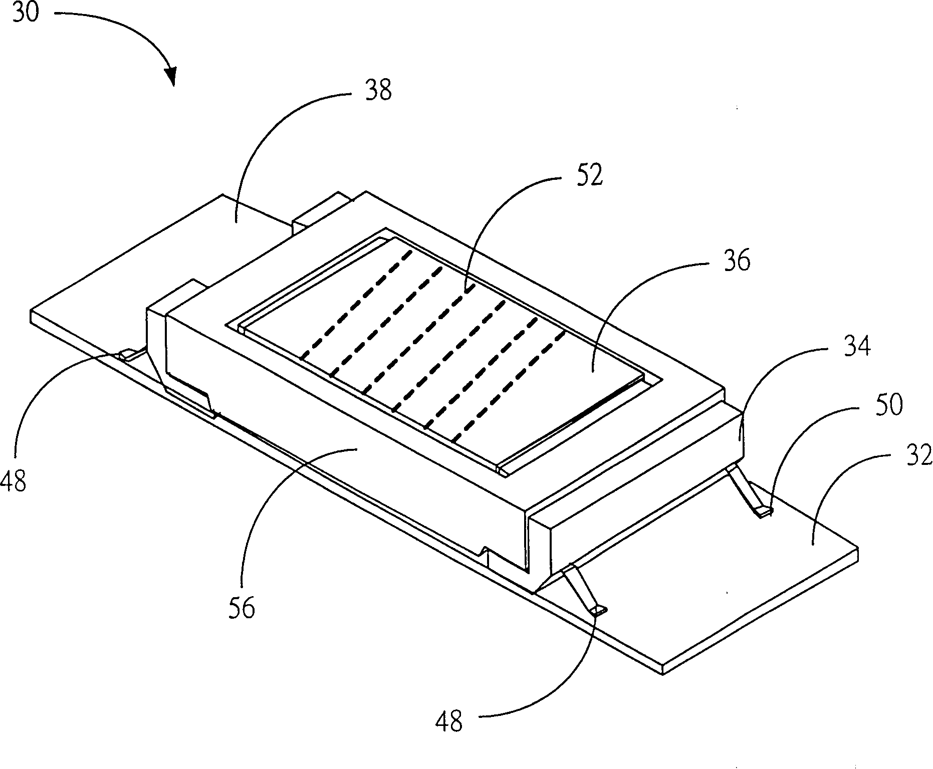
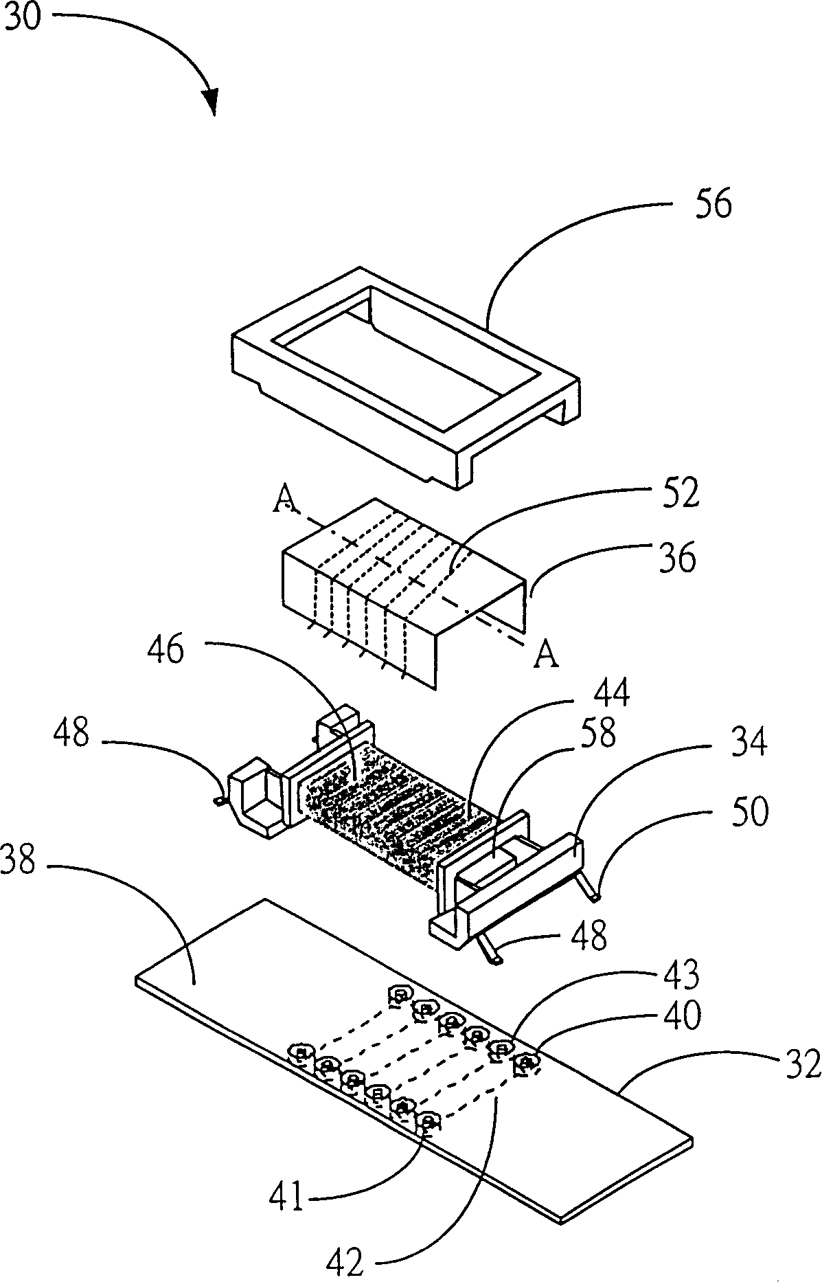
[0014] see figure 2 and image 3 , figure 2 is a schematic diagram of the transformer 30 of the present invention, image 3 for figure 2 A combined element diagram of the transformer 30 is shown. The transformer 30 of the present invention includes a base plate 32 , a bobbin body 34 and a wire device 36 . The substrate 32 can be a single-layer, double-layer or multi-layer printed circuit board (Printing Circuit Board), here take a double-layer printed circuit board as an example, wherein the substrate 32 defines a front 38 and a back 39 (not shown), the substrate 32 It includes a plurality of pads (Pads) 40 and a plurality of lower wires 42 . Each pad 40 is disposed on the substrate 32 and used as an electrical connection point between the front side 38 and the back side 39 of the substrate 32 , wherein each pad 40 may be a copper foil penetrating through the substrate 32 . Each lower wire 42 is disposed on the back surface 39 of the substrate 32 for electrically conn...


PUM


Abstract

A transformer with high coupling efficiency is composed of base plate, wire-winding axle body and conducting wire unit. Said base plate has multiple welding pads used for electric connections between front and back surfaces, and multiple lower conducting wires on its back for connecting two welding pads. Said wire-winding axle body is used for high-voltage conducting wires. Said conducting wire unit on said wire-winding body has multiple upper conducting wires connected to welding pads. Said upper and lower conducting wires are connected with each other to form a low-voltage loop.

Description

technical field [0001] The invention relates to a transformer, in particular to a transformer with high coupling efficiency. Background technique [0002] Chip Coil Transformer (Chip Coil Transformer) is an important component of a common Surface Mounting Technology (Surface Mounting Technology), which is usually mounted on a circuit board (Circuit Board) to provide various voltages required in the circuit. [0003] see figure 1 , figure 1 It is a schematic diagram of an existing chip transformer 10 . The conventional chip transformer 10 includes a bobbin body (Bobbin) 12 , a low voltage wire 13 , a high voltage wire 14 and an iron core 15 . A plurality of partitions 16 and a plurality of pins 17 are disposed on the bobbin body 12 . A coil winding area 18 is formed between every two separators 16, wherein there are seven coil winding areas 18-24 on the winding shaft body 12, as figure 1 shown. The low-voltage wire 13 is wound in the coil winding area 18 and forms a low...

Claims


Application Information

Patent Timeline
Patent Type & Authority Patents(China)
IPC IPC(8): H01F19/00H01F30/06
Inventor 江升隆薛景福
Owner DARFON ELECTRONICS CORP
Features
  • R&D
  • Intellectual Property
  • Life Sciences
  • Materials
  • Tech Scout
  • Unparalleled Data Quality
  • Higher Quality Content
  • 60% Fewer Hallucinations
Learn More