
Power supply system, power supply method, electronic equipment and storage medium

A technology of power supply system and load equipment, which is applied in the direction of electric energy storage system, power network operating system integration, battery circuit device, etc. It can solve the problems of restricting the use of photovoltaic power generation devices, photovoltaic power generation devices cannot work together, and the proportion is not high.

Pending Publication Date: 2022-03-11
GREE ELECTRIC APPLIANCES INC +1
View PDF0 Cites 0 Cited by
  • Summary
  • Abstract
  • Description
  • Claims
  • Application Information

AI Technical Summary

Problems solved by technology

[0002] With the concept of "carbon neutrality", in order to abandon the environmental impact of traditional power generation, more and more people advocate the use of solar power or wind power. The development of solar power technology has become more and more mature, but the actual In residential use, the proportion is not high. The main problem is that solar power generation requires a certain area to collect solar energy. Except for villas, few residents have enough area to meet the area demand for solar power generation. Inability to work together also limits the use of photovoltaic power generation devices

Method used


Image

  • Power supply system, power supply method, electronic equipment and storage medium
  • Power supply system, power supply method, electronic equipment and storage medium
  • Power supply system, power supply method, electronic equipment and storage medium

Examples


Embodiment Construction

[0044] In order to make the purposes, technical solutions and advantages of the embodiments of the present application clearer, the technical solutions in the embodiments of the present application will be clearly and completely described below in conjunction with the drawings in the embodiments of the present application. Obviously, the described embodiments It is a part of the embodiments of this application, but not all of them. Based on the embodiments in the present application, all other embodiments obtained by persons of ordinary skill in the art without making creative efforts belong to the protection scope of the present application.

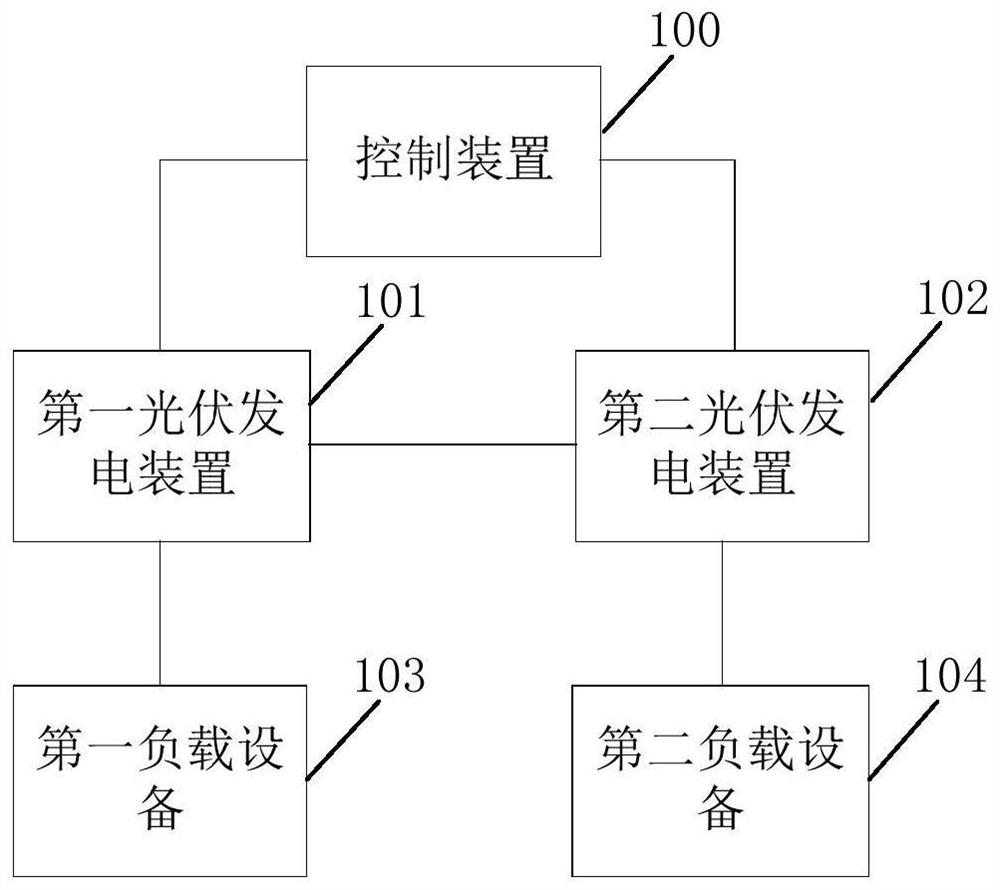
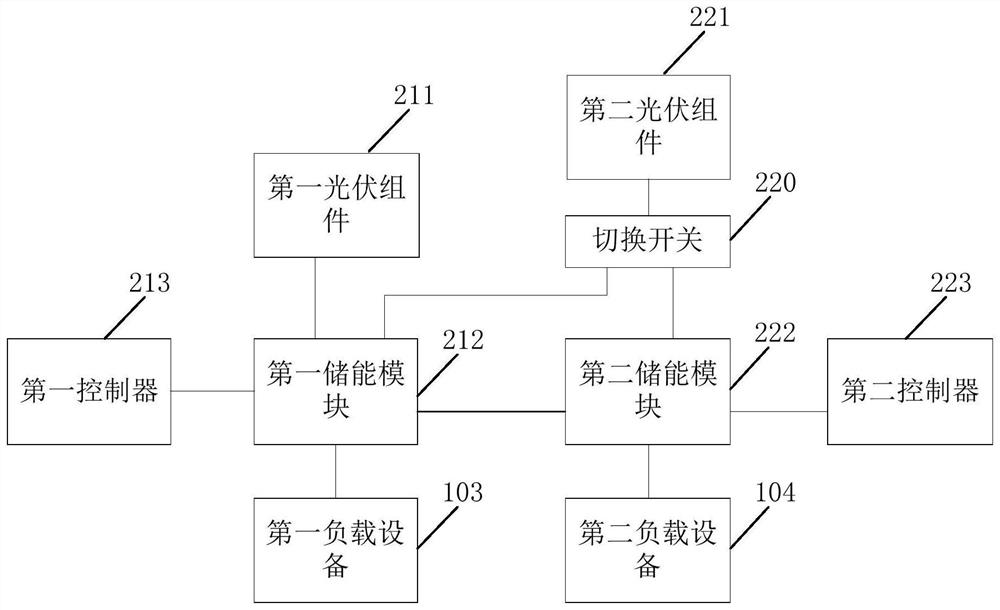
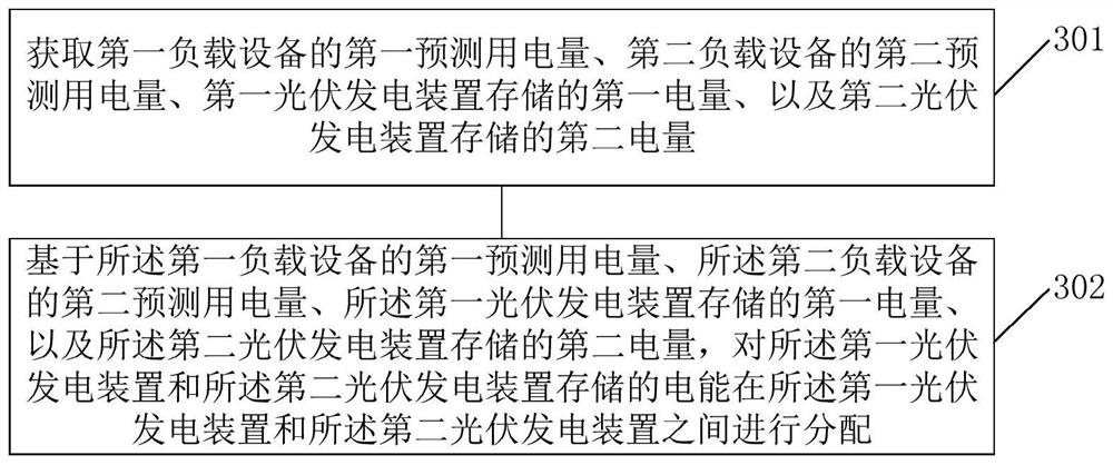
[0045] The first embodiment of the present application provides a power supply system, such as figure 1, the power supply system includes a control device 100, a first photovoltaic power generation device 101 and at least one second photovoltaic power generation device 102; the second photovoltaic power generation device 102 is connecte...


PUM


Abstract

The invention relates to a power supply system, a power supply method, electronic equipment and a storage medium, and belongs to the technical field of new energy. The power supply system comprises a first photovoltaic power generation device and at least one second photovoltaic power generation device, the second photovoltaic power generation device is connected to the first photovoltaic power generation device; the first photovoltaic power generation device is used for converting collected solar energy into electric energy, storing the electric energy and supplying power to the first load equipment; the second photovoltaic power generation device is used for converting the collected solar energy into electric energy, storing the electric energy and supplying power to the second load equipment; the first photovoltaic power generation device is further used for generating power based on the first predicted power consumption of the first load device, the second predicted power consumption of the second load device, the first electric quantity stored by the first photovoltaic power generation device and the second electric quantity stored by the second photovoltaic power generation device. The electric energy stored by the first photovoltaic power generation device and the second photovoltaic power generation device is distributed, the problem of electric quantity distribution of the photovoltaic power generation devices is solved, and the user experience is improved.

Description

technical field [0001] The present application relates to the field of new energy technologies, and in particular to a power supply system, a power supply method, electronic equipment, and a storage medium. Background technique [0002] With the concept of "carbon neutrality", in order to abandon the environmental impact of traditional power generation, more and more people advocate the use of solar power or wind power. The development of solar power technology has become more and more mature, but the actual In residential use, the proportion is not high. The main problem is that solar power generation requires a certain area to collect solar energy. Except for villas, few residents have enough area to meet the area demand for solar power generation. The inability to work together also limits the use of photovoltaic power generation devices. Contents of the invention [0003] In order to solve the technical problem of cooperative operation among photovoltaic power generat...

Claims


Application Information

Patent Timeline
IPC IPC(8): H02J7/35H02J7/00H02J9/06H02J9/02H02J15/00H02J3/00
CPCH02J7/35H02J7/0048H02J9/06H02J9/065H02J9/02H02J15/00H02J3/003H02J3/0075H02J2310/14Y02E10/56Y02E70/30Y02B10/70Y02B70/30Y02B70/3225Y04S20/20Y04S20/222
Inventor 詹培旋李梦瑶王彬贾巨涛宋德超
Owner GREE ELECTRIC APPLIANCES INC
Learn More