
Eureka
For R&D, Eureka makes reading and utilizing patents & technical documents easy.
Eureka AIR
Designed for self-driven R&D workflows. Generate viable solutions, solve complex R&D challenges, empower your innovation with AI.

Eureka Materials
Designed for material experts only. Revolutionize your material R&D, from search, analyze, to developing new materials.

TechResearch
Generate reliable direction feasibility study reports for your R&D in just a few steps.

TechSeek
Discover and master advanced knowledge NOW. Basics, ideas, possibilities, all at once.

TechMind
As an expert in R&D Theories, TechMind can generates customized viable solutions instantly.

TechRisk
Analyze your overall solution with one click, know your potential R&D risks in advance.

TechMonitor
Get weekly tech updates, stay abreast of the latest tech innovations and key insights.
Vehicle-mounted camera and manufacturing method thereof
A vehicle-mounted camera and substrate technology, which is applied in the direction of cameras, camera bodies, vehicle components, etc., can solve problems such as inapplicable tilt adjustment, achieve good focusing accuracy, and suppress displacement
- Summary
- Abstract
- Description
- Claims
- Application Information
AI Technical Summary
Problems solved by technology
Method used
Image

Examples
Embodiment Construction
[0048] Hereinafter, embodiments of the present technology will be described with reference to the drawings.
[0049] First, the configuration of a typical vehicle-mounted camera and its problems will be described, and then an embodiment of the vehicle-mounted camera according to the present technology will be described.
[0050] [Typical car camera configuration and its problems]
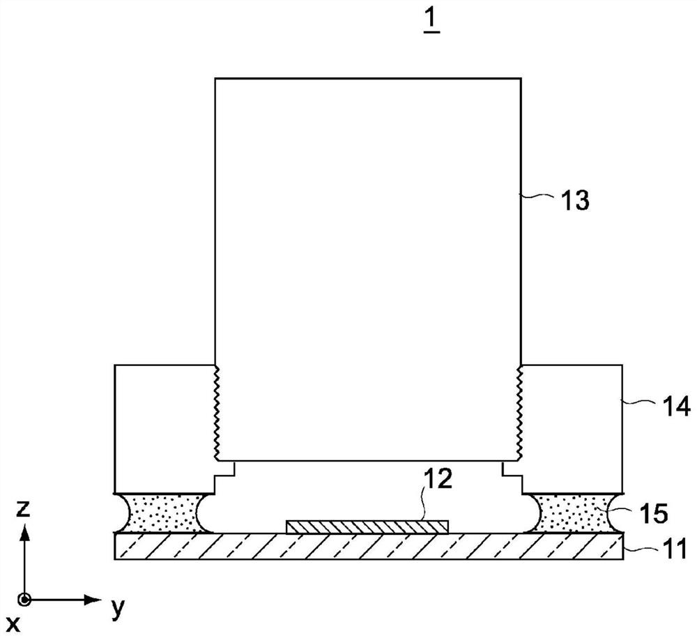
[0051] figure 1 is a cross-sectional view showing the configuration of a typical vehicle-mounted camera 1 .
[0052] As shown in the figure, this typical vehicle-mounted camera 1 includes a substrate 11 , an imaging device 12 mounted on one surface of the substrate, a lens unit 13 , and a bracket 14 holding the lens unit 13 . An imaging device 12 such as a CMOS image sensor or a CCD image sensor is mounted on the main surface of the substrate 11 . The bracket 14 is a metal bracket 14 made of, for example, aluminum die-cast, and is configured to hold the outer periphery of the lens unit 13 . The ...
PUM
 Abstract
Description
Claims
Application Information
 - R&D Engineer
- R&D Manager
- IP Professional
- Industry Leading Data Capabilities
- Powerful AI technology
- Patent DNA Extraction
Browse by: Latest US Patents, China's latest patents, Technical Efficacy Thesaurus, Application Domain, Technology Topic, Popular Technical Reports.
© 2024 PatSnap. All rights reserved.Legal|Privacy policy|Modern Slavery Act Transparency Statement|Sitemap|About US| Contact US: help@patsnap.com