Oral cavity flushing device for department of stomatology

A technology of irrigation device and stomatology, applied in the medical field, can solve problems such as patient discomfort, and achieve the effect of reducing cumbersomeness and ease of use

Inactive Publication Date: 2022-03-15
郑州市口腔医院
View PDF0 Cites 0 Cited by
  • Summary
  • Abstract
  • Description
  • Claims
  • Application Information

AI Technical Summary

Problems solved by technology

Before treating oral diseases, stomatologists need to clean up the inside of the patient's mouth, remove inflammatory secretions, food residues, tartar, etc. attached to the wound, oral mucosa, gums, and interdental spaces, so as to achieve treatment, cleaning, and prevention of secondary disease. For the purpose of infection, in order to facilitate the operation of the inside of the oral cavity, medical personnel need to rinse these secretions and tartar and other sundries. The existing flushing equipment generally uses cleaning liquid, which is sprayed by high pressure to the patient's oral cavity. The interior is cleaned, and the cleaning solution will leave liquid and debris in the mouth after cleaning the mouth, which will cause discomfort to the patient after the cleaning solution accumulates, or even swallow the cleaning solution and debris after the patient's voluntary swallowing action Therefore, for the protection of the patient, if the patient can spit out the cleaning solution and debris under their own control and rinse their mouth with mouthwash, and if the patient cannot operate, the medical staff needs to remove the debris in the patient's mouth. The objects and cleaning fluid are sucked out, and the post-cleaning treatment requires the cooperation of multiple equipment and pipelines and multiple staff members.

Method used


Image

  • Oral cavity flushing device for department of stomatology
  • Oral cavity flushing device for department of stomatology
  • Oral cavity flushing device for department of stomatology

Examples


Embodiment Construction

[0027] The following will clearly and completely describe the technical solutions in the embodiments of the present invention with reference to the accompanying drawings in the embodiments of the present invention. Obviously, the described embodiments are only some, not all, embodiments of the present invention. Based on the embodiments of the present invention, all other embodiments obtained by persons of ordinary skill in the art without making creative efforts belong to the protection scope of the present invention.

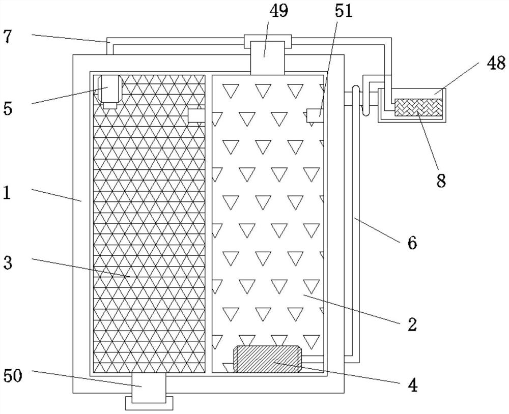
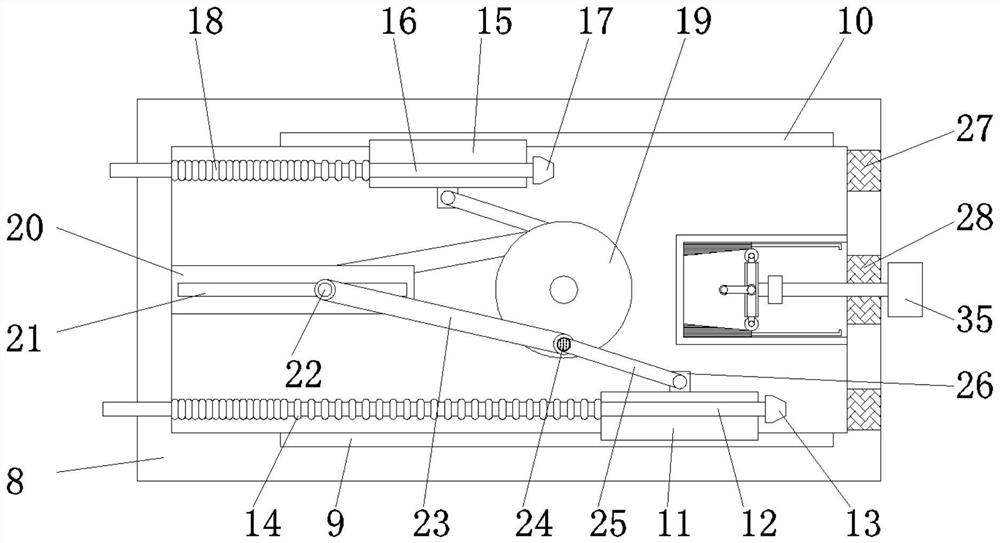
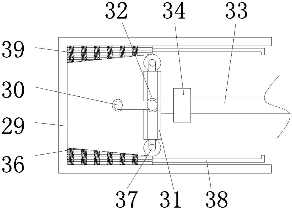
[0028] Such as Figure 1-5As shown, the present invention provides a technical solution: a dental oral irrigation device, comprising a liquid storage tank 1, a liquid storage tank 1, a cleaning tank 2, a sewage tank 3, and a cleaning tank 2 are placed inside the liquid storage tank 1 The inside of the sewage tank 3 is fixedly connected with a booster pump 4, the inside of the sewage tank 3 is fixedly connected with a suction pump 5, the output end of the boost...


PUM


Abstract

The invention relates to the technical field of medical treatment, and discloses an oral cavity flushing device for the stomatology department, the oral cavity flushing device comprises a liquid storage tank, the liquid storage tank is internally provided with a cleaning tank and a sewage tank, the interior of the cleaning tank is fixedly connected with a booster pump, the interior of the sewage tank is fixedly connected with a suction pump, and the suction pump is fixedly connected with the booster pump. The output end of the booster pump is fixedly connected with a high-pressure hose, and the output end of the suction pump is fixedly connected with a sewage hose. Cleaning liquid in the cleaning box is conveyed to the high-pressure hose through the booster pump, tooth dirt and impurities in the oral cavity are cleaned through the high-pressure spray head in a high-pressure mode, and then the suction pump enables the suction spray head to generate suction force to suck the impurities and the cleaning liquid in the oral cavity into the sewage box to be stored. The high-pressure spray head and the suction spray head are designed in one cleaning device, so that one worker can operate the cleaning and suction treatment process, the complexity of equipment is reduced, and the device is convenient to use by the worker.

Description

technical field [0001] The invention relates to the field of medical technology, in particular to an oral irrigation device for stomatology. Background technique [0002] In the Department of Stomatology, oral diseases are characterized by high incidence, wide patient population, and popularity, and have become popular and frequently occurring diseases. Before treating oral diseases, stomatologists need to clean up the inside of the patient's mouth, remove inflammatory secretions, food residues, tartar, etc. attached to the wound, oral mucosa, gums, and interdental spaces, so as to achieve treatment, cleaning, and prevention of secondary disease. For the purpose of infection, in order to facilitate the operation of the inside of the oral cavity, medical personnel need to rinse these secretions and tartar and other sundries. The existing flushing equipment generally uses cleaning liquid, which is sprayed by high pressure to the patient's oral cavity. The interior is cleaned,...

Claims


Application Information

Patent Timeline
Patent Type & Authority Applications(China)
IPC IPC(8): A61C17/02A61B1/24A61B1/04A61B1/12
CPCA61C17/0202A61C17/0208A61B1/24A61B1/04A61B1/125A61B1/123
Inventor 陈营杰
Owner 郑州市口腔医院
Why Eureka
Try Eureka