Supercharge Your Innovation With Domain-Expert AI Agents!

Skin medicine smearing device for patients in burn department

A drug and patient technology, which is applied in the field of skin drug application devices for burn patients, can solve the problems of reduced work efficiency, uneven drug application, uneven susceptibility to force, etc., and achieve the effect of reducing taking

Pending Publication Date: 2022-03-15
谢鹏花
View PDF0 Cites 2 Cited by
  • Summary
  • Abstract
  • Description
  • Claims
  • Application Information

AI Technical Summary

Problems solved by technology

[0005] In order to overcome the shortcomings of currently applying medicine to the burnt skin of patients, doctors generally rely on doctors to manually smear the burned skin of patients, the work efficiency is reduced, and the patient's limbs are suspe

Method used


Image

  • Skin medicine smearing device for patients in burn department
  • Skin medicine smearing device for patients in burn department
  • Skin medicine smearing device for patients in burn department

Examples


Embodiment 1

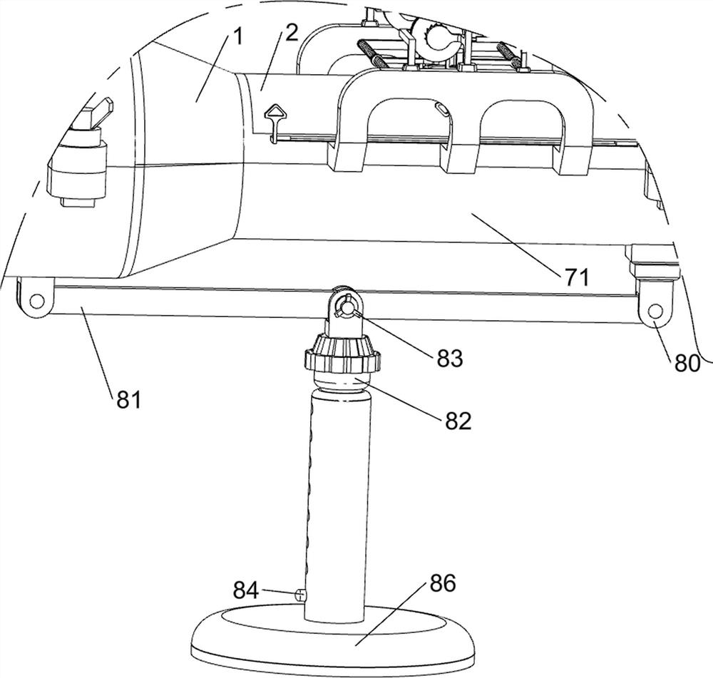
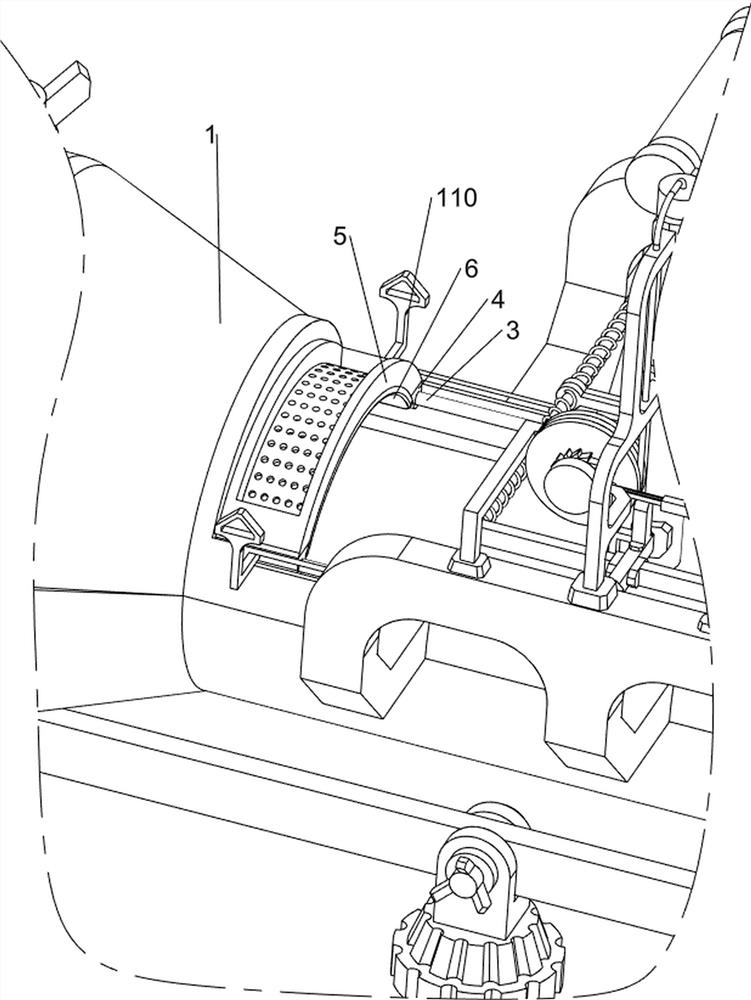
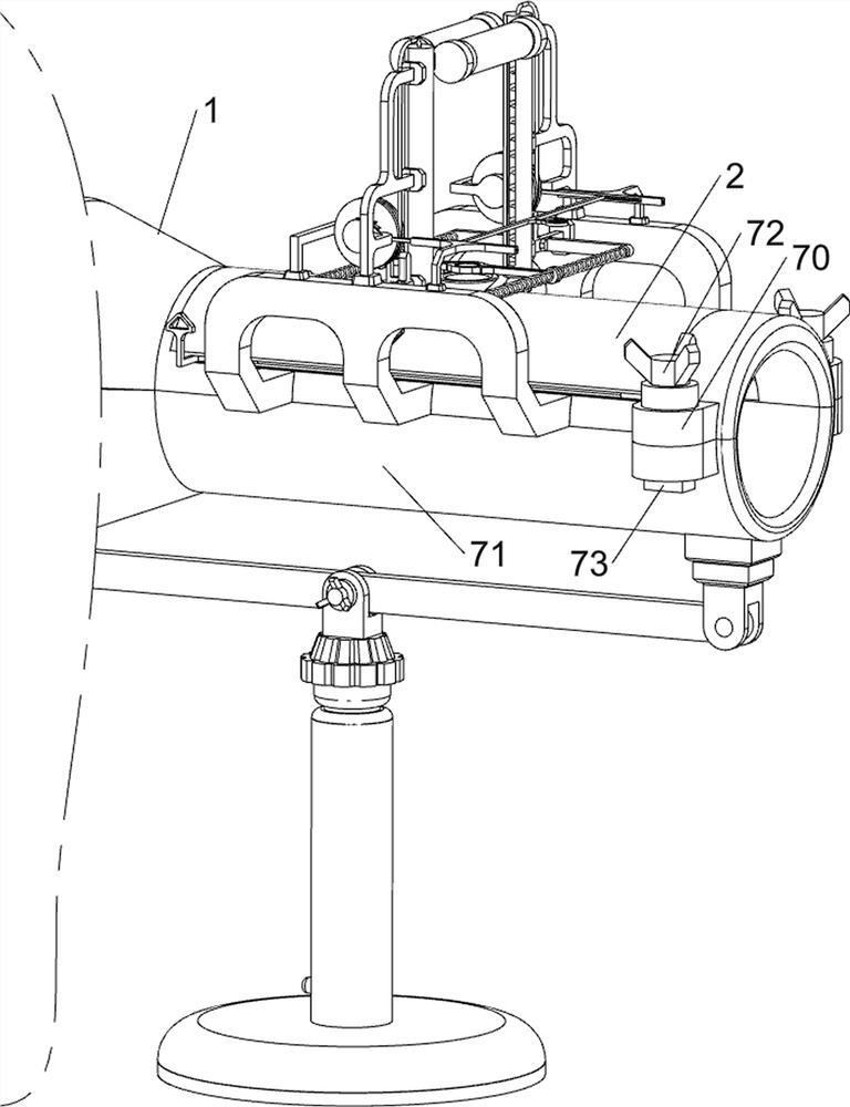
[0080] A skin drug application device for burn patients, such as Figure 1-Figure 5 As shown, it includes a first support plate 1, a protective plate 2, an electric slide rail 3, an electric push block 4, a placement plate 5, a sponge cloth 6, a fixing mechanism 7 and an adjustment mechanism 8, and the upper right side of the first support plate 1 slides The protective plate 2 is provided to protect the patient. Electric slide rails 3 are installed on the front and rear sides of the upper part of the first support plate 1. The left sides of the two electric slide rails 3 are slidingly provided with electric push blocks 4. , a placement plate 5 is arranged between the two electric push blocks 4 for placing medicines, 75 through holes are opened on the placement plate 5 for the medicine to flow, and a sponge cloth 6 is provided at the bottom of the placement plate 5 for Apply medicine to the patient's skin, the bottom of the first support plate 1 is provided with a fixing mechan...

Embodiment 2

[0087] On the basis of Example 1, such as figure 1 , figure 2 , Figure 6 , Figure 7 , Figure 8 , Figure 9 , Figure 10 , Figure 11 , Figure 12 , Figure 13 and Figure 14 As shown, an extrusion mechanism 9 is also included, and the extrusion mechanism 9 includes a support frame 90, a fourth support seat 91, a first limit block 92, a second support block 93, a first return spring 94 and an extrusion cylinder 95 , the front and rear sides of the first support plate 1 are provided with support frames 90, the tops of the two support frames 90 are provided with fourth support seats 91, and the inner ends of the two fourth support seats 91 are provided with first limiting blocks 92, Two first limit blocks 92 are connected with the support frame 90 on the same side, and the second support blocks 93 are slidably arranged on the tops of the two first limit blocks 92, and the two second support blocks 93 are rotatably provided with two An extruding cylinder 95 is used t...


PUM


Abstract

The invention relates to a skin medicine applying device, in particular to a skin medicine applying device for a patient in the burn department. According to the skin medicine smearing device for the patient in the burn department, the limbs of the patient can be supported, meanwhile, medicine can be automatically smeared on the limbs of the patient, and the working efficiency is improved. According to the technical scheme, the skin medicine smearing device for the patient in the burn department is characterized in that a protection plate is arranged on the right side of the upper portion of a first supporting plate in a sliding mode; the electric sliding rails are mounted on the front side and the rear side of the upper part of the first supporting plate; the electric push blocks are arranged on the left sides of the two electric slide rails in a sliding manner; and the placing plate used for placing medicines is arranged between the two electric push blocks. The limbs of the patient can be supported through the second supporting plate, and the situation that in the medicine applying process of the patient, the limbs are suspended in the air all the time, but the limbs are prone to uneven stress, and medicine applying is uneven is reduced.

Description

technical field [0001] The invention relates to a skin drug application device, in particular to a skin drug application device for burn patients. Background technique [0002] Burns generally refer to tissue damage to the skin caused by heat, high temperature, steam, etc., mainly referring to skin and mucous membrane damage. Severe burns generally cause systemic infection and lung infection. Severe burns can cause shock. The formation of a large area of ​​scars can affect joint movement. [0003] At present, for the skin treatment of burn patients, the doctor first judges the severity of the burn on the patient's burn site, and then uses medicine on the patient's skin according to the degree of burn. Currently, the doctor uses tweezers to clamp the cotton to contaminate the patient's skin. However, when the doctor applies the medicine to the patient's skin, the patient needs to hang the limbs in the air. However, the limbs maintain the same movement for a long time, and th...

Claims


Application Information

Patent Timeline
IPC IPC(8): A61M35/00A61G12/00
CPCA61M35/20A61G12/00A61M2210/04A61M2210/005
Inventor 谢鹏花
Owner 谢鹏花
Features
  • R&D
  • Intellectual Property
  • Life Sciences
  • Materials
  • Tech Scout
  • Unparalleled Data Quality
  • Higher Quality Content
  • 60% Fewer Hallucinations
Learn More