Method for mixing two-component polyurea by using spray gun and special spray gun thereof

A two-component, spray gun technology, applied to spray devices, liquid spray devices, etc., can solve the problems of heavy weight, large volume, difficult movement and transportation of polyurea waterproof construction equipment, achieve quality assurance, improve mixing rate, reduce The effect of weight

Pending Publication Date: 2022-03-15
广西宁铁地产发展有限公司
0 Cites 0 Cited by

AI-Extracted Technical Summary

Problems solved by technology

[0002] At present, the water seepage of exterior walls, bathrooms and roofs commonly exists in various residential buildings after construction delivery. Although the existing polyurea waterproof materials can effectively solve this problem, the two-component materials Group A and Group B are in contact with the air. Mixing in a connecte...

Abstract

According to the method for mixing the bi-component polyurea in the spray gun and the bi-component polyurea spray gun, an A-group feeding pipe and a B-group feeding pipe are connected with a feeding port of a coupler, the coupler is connected with a mixing cavity, the mixing cavity is of a tubular structure, and the front end of the mixing cavity is connected with a discharging port of the coupler, so that materials sent out from the two discharging ports of the coupler are mixed in the mixing cavity; a plurality of X-shaped static mixers are installed in an inner hole of the tubular structure of the mixing cavity, and the rear end of the mixing cavity is connected with an atomizer. The double-component material mixing device has the advantages that double-component materials A and B which are mixed in the air originally are changed to be mixed in the mixing cavity, and the two materials can be mixed according to the proportion required by related technologies by respectively controlling the feeding speed and the feeding quantity of the materials A and B, so that the weight of the whole system equipment can be reduced, and the production cost is reduced. The double-component material is ensured to be mixed according to the proportion required by the technology, the mixing rate of the material A and the material B is improved, and the quality of the formed polyurea elastomer is further ensured.

Application Domain

Liquid spraying apparatus

Technology Topic

PolyureaManufacturing engineering +5

Image

  • Method for mixing two-component polyurea by using spray gun and special spray gun thereof
  • Method for mixing two-component polyurea by using spray gun and special spray gun thereof
  • Method for mixing two-component polyurea by using spray gun and special spray gun thereof

Examples

  • Experimental program(1)

Example Embodiment

[0023] The present invention is further elaborated and explained in connection with the specific embodiments and description.
[0024] In order to make the objects, technical solutions and advantages of the present invention, the present invention will be further described in detail below with reference to the accompanying drawings. Obviously, the described embodiments are merely the embodiments of the invention, not all of the embodiments. Based on the embodiments of the present invention, all other embodiments obtained by those of ordinary skill in the art are in the range of the present invention without making creative labor premise.
[0025] In the description of the present invention, it is to be understood that the orientation or positional relationship indicated by "upper", "lower" "horizontal", "within", "outside", etc. is based on the orientation or positional relationship shown in the drawings. It is only to facilitate the description of the present invention and simplified description, rather than indicating or implying that the device or element must have a particular orientation, and therefore, it is not understood to be limited to the present invention.
[0026] A two-component polyurea is a method of mixing with a spray gun, comprising the steps:
[0027] (1) Two-component polyurea Group A and B group feed control step: the amount of feed tube of the bicomponent polyurea A and Group B is controlled in the spray gun feed tube. The speed is controlled to ensure that the two materials can be mixed according to the proportion of the relevant technical requirements; the pressure monitoring switch is set in the group B group, and the control Switch controls the group A and B groups. The feed pressure value is 0.4 kPa-4kPa, thereby controlling the compound ratio of the group A and the B group;
[0028] (2) Two-component coupling steps: In the export of the gun feed tube, the two sets from the A group from the spray gun and the group B will be sent to the discharge port of the group A with the B group. Mixed cavity;
[0029] (3) Mixed step: In the diameter φ9-10mm lumen, multiple SX static mixers are mixed, and the mixing mode of multiple SX static mixers is: multiple SX static mixers are arranged along the tube cavity. A row of mounted, adjacent SX static mixers use a horizontal vertical alternate placement;
[0030] (4) Atomization step: The mixed group A is sent to the group B for atomizing, and then ejectively ejected.
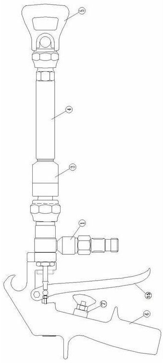
[0031] Please refer to figure 1 , figure 2 , image 3 , Figure 4 According to a two-component polyurea dedicated spray gun, including a gun handle 6, a component feed tube 1 and B, the A group of feed tube 1 and B group feed 2 connecting a coupling 3 Feed port, the two discharge ports of the coupling 3 are smaller than the spacing of the feed port, forming a contracted structure; two discharge ports of the coupling 3 connect the mixing chamber 4, the mixing chamber 4 is a tubular structure, and the front end is connected to the coupling port such that the material sent from the two discharge ports of the coupling 3 is mixed in the mixing chamber, and 17 X-type static mixers are installed in the mixing chamber structure inner hole. The rear end of the mixing chamber 4 is attached to the atomizer 5; the mixing chamber 4 is a φ9-10 mm lumen for the Group B, and the 17 X-static mixers placed in the mixing chamber 4 are adjacent. SX Static Mixer One Horizontal SX Static Mixer 13 One Vertical Sx Static Mixer 14 Alternate Placement, such as Figure 4 As shown, the spray gun 6 sets the total control switch 7 to control the entire system; the total control switch 7 is located at the rear end of the spray gun switch, and after the spray gun switch 15 is swoled, the compression total control switch 7 is turned on, the control system Work, after the spray gun switch 15 is separated, the total control switch 7 is turned off, and the control system stops working.
[0032] The coupling 3 is a transition device that is coupled to the charge tube 1 and the B group of feed tube 2 and the mixing chamber 4, which makes two separate input ports to be combined into an outlet that can be coupled to the mix cavity 4. Union with the mixing chamber 4; the end of the coupling 3 is the outer threaded structure, and the mixing chamber inlet end 11 of the mixing chamber 4 is a threaded hole, and the coupling 3 is fastened by the threaded structure and the mixing chamber 4. The coupling 3 sets the b interface 7 of the A interface 6 and φ10 mm of φ10 mm. The exit provided on the other end is two φ3mm incompatible through holes, the first hole 8, the second hole 9, and the second hole 9 is provided with a thickness of 1 mm long 10 mm, and the resilient plate 10 is a front extension, and the front end extension To the mixing chamber 4, the staper plate 10 can prevent the material from which the first hole 8 and the second hole 9 is not sufficiently mixed, resulting in the clogging of the two holes.
[0033] The A group feed tube 1 is provided with a pressure monitoring switch on the b tube 2, respectively, and monitors the feed pressure of the Group B in group B. Through this pressure monitoring switch controls the feed pressure value of the group B and the B group, by controlling the flow rate and speed of the A material and B material to enter the system, thereby controlling the amount of feed ratio of Group B. .
[0034] The mixing chamber outlet end 12 of the front end of the mixing chamber 4 is connected to the atomizer 5.
[0035] When the present invention is used, the spray gun switch 15 is swinghed backwards, and the press control switch 7 is powered by power, the A component, the B group is respectively supplied from the A group feed tube 1, and the B group feed tube 2 is pressed under the control of the pressure monitoring switch. The ratio enters the coupling 3, and the component B is fed into the mixing chamber 4 by the coupling 3, and after the mixing chamber 4 is mixed, the nebulizer 5 is outward. Eject.
[0036] It will be noted that the above embodiments are intended to illustrate the technical solutions of the present invention, and not to the scope of the invention, although the present invention will be described in detail, and those skilled in the art will understand The technical solution of the present invention can be modified or equivalent to replacement without departing from the spirit and scope of the present invention.

PUM

no PUM

Description & Claims & Application Information

We can also present the details of the Description, Claims and Application information to help users get a comprehensive understanding of the technical details of the patent, such as background art, summary of invention, brief description of drawings, description of embodiments, and other original content. On the other hand, users can also determine the specific scope of protection of the technology through the list of claims; as well as understand the changes in the life cycle of the technology with the presentation of the patent timeline. Login to view more.

Similar technology patents

Refrigerator drawer and refrigerator applying same

InactiveCN103851871AGood product experience effectreduce weight
Owner:HISENSE(SHANDONG)REFRIGERATOR CO LTD

Plastic coated metal fuel rail

InactiveUS20060162697A1reduce weightreduce weight of vehicle
Owner:DANA AUTOMOTIVE SYST GRP LLC

Severe plastic deformation technology of magnesium alloy board

ActiveCN103276328AImprove productivity and qualityreduce weight
Owner:UNIV OF JINAN

New megapixels wide-angle lens

ActiveCN101587232Areduce weightlow cost
Owner:NINGBO SUNNY AUTOMOTIVE OPTECH

Classification and recommendation of technical efficacy words

  • reduce weight

Electrically driven brake booster

InactiveUS20020158510A1reduce weightsimple construction
Owner:BOSCH AUTOMOTIVE SYST CORP

Display device

ActiveUS20140043546A1reduce weightreduce detection sensitivity
Owner:SEMICON ENERGY LAB CO LTD

Curved Automatic-Darkening Filter

InactiveUS20140168546A1reduce weightlow weight
Owner:3M INNOVATIVE PROPERTIES CO

Thermal Solution for Prismatic Lithium Ion Battery Pack

ActiveUS20130115506A1reduce weight
Owner:NEOGRAF SOLUTIONS LLC
Why Eureka
Try Eureka